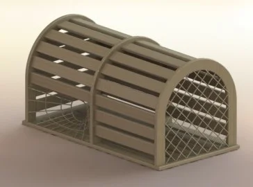

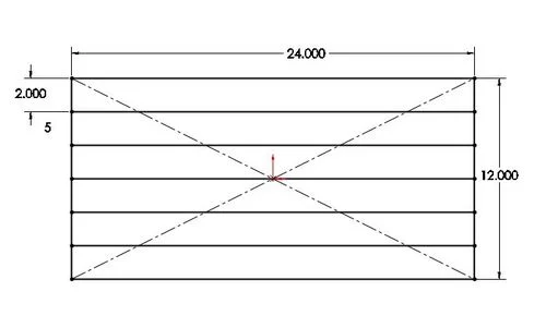
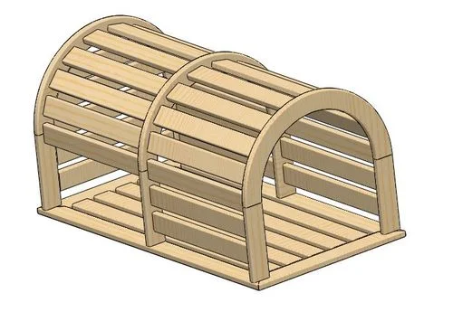
This time I decided to make a part using the weldments feature and explain how I went about it. I made a lobster trap using only weldments. Even though this lobster trap is made out of wood, weldments still can be useful as the wood used here is all a constant profile. Through the use of weldments, a cut list can be generated which is also a good thing to have when working with wood. To make it, I first started off by making a sketch of the bottom of the trap. This was done on the top plane and all the lines of where the planks would go were included. This sketch can be seen below.
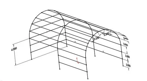
Next a 3D sketch was created for the rest of the planks in the trap. This was done using three arches and then connecting them with equal spaced lines. The lines represent where the planks will go so it is necessary to make sure that the profile of the weldment will fit without over lapping. This 3D sketch can be seen below.
After the whole profile is created weldments can be added. Under insert, click weldments and then structural members. For this part I used ansi inch for the standard, rectangular tubing for the type, and 3 x 2 x 0.25 as a basis for the size of the pieces of wood. This profile was then modified after the weldments were created by going under the drop down for the weldment in the feature manager and editing the sketch. Groups need to be created for clusters of lines. The lines in each group either need to be a continuous loop or else they need to all be parallel. For the main part of the lobster trap I ended up using 15 different groups. I started off by selecting the outside rectangle of the bottom as my first group. More groups were created until all the sketch lines were in groups. Groups can also be rotated or aligned by using the option at the bottom of the feature manager. This is what the screen looks like when placing all the weldments.
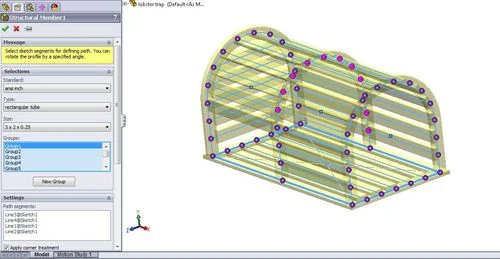
The purple dots that show up are all the intersection points of the structural members. If a joint meets up a different way than is desired, the purple dot can be selected and then the trimming order of the groups can be changed. This changes which member is cut first at that joint. Once all the members are placed as desired click the check mark and it will look something like this.
The netting was created using more sketches and weldments. However, the desired profile for the weldments was not a choice under the sizes. To get around this, a random size was chosen and then after the members were selected the profile could be changed. This is able to be done under the drop down for the structural members and then editing the sketch of the profile. I made this profile a 0.125 inch diameter circle. My sketches for the netting can be observed by downloading my part that is attached below. I hope this inspires you to start your own project with weldments. Enjoy!
Ian Jutras
Worcester Polytechnic Institute
Mechanical Engineering 2013