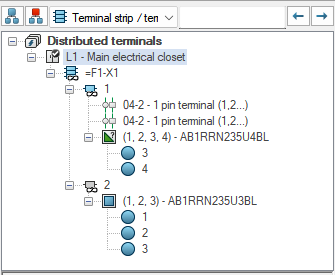

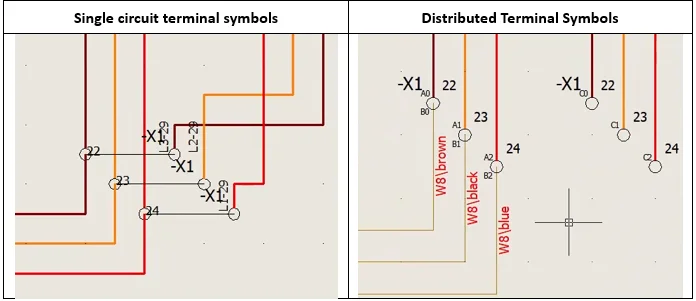
The Distributed Terminals project introduces greater flexibility in how terminal components, such as junction blocks, are represented in a schematic.
Until now, all the connection points of a circuit had to be shown on one single symbol. With this update, you can distribute those connection points across multiple symbols and pages as needed in the design.
This kind of flexibility already exists in entry-level electrical CAD tools. Bringing it into a high-end, database-driven application like SOLIDWORKS Electrical means you get both: the power of the database and the freedom to lay things out the way you want.
This kind of flexibility already exists in entry-level electrical CAD tools. Bringing it into a high-end, database-driven application like SOLIDWORKS Electrical means you get both: the power of the database and the freedom to lay things out the way you want.
Terminal components and junction blocks
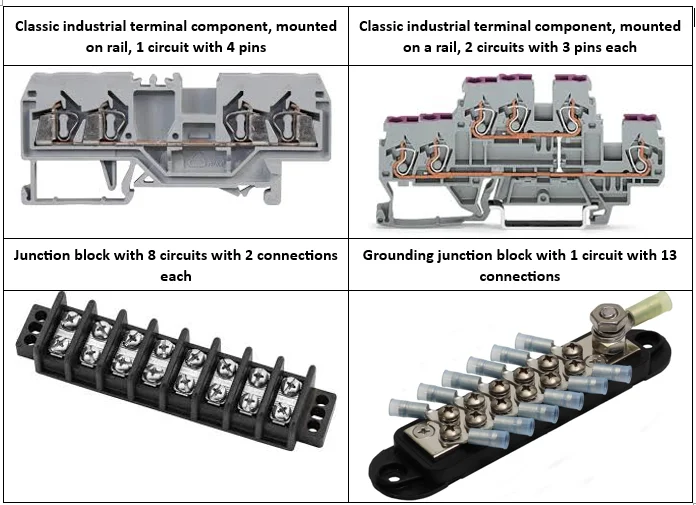
A terminal component, also called a junction block, is used to connect wires and cables together. It can be made of one or several circuits, and each circuit is an equipotential connection. Most circuits have two connections, but some have a dozen or more.
A few common examples:
Support for partial symbols
The idea behind the project is to bring flexibility to how terminal component symbols are inserted. The key to that is support for partial symbols. When a symbol can represent only a part of a component circuit, you can split the circuit connections across several places or pages.
Symbol insertion, selecting a specific pin
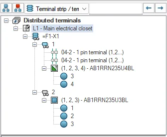
When you insert a terminal symbol, you can now select not only the circuit to use, but also a specific pin. Before, only the whole circuit, with all its pins, could be selected. This is what makes partial symbols possible.
The component tree reflects it too. Terminals of the same circuit are grouped together, and a circuit that is only partly used shows a half-colored, half-grey icon so you can see and pick only the free terminals.
A new list of pins in component properties
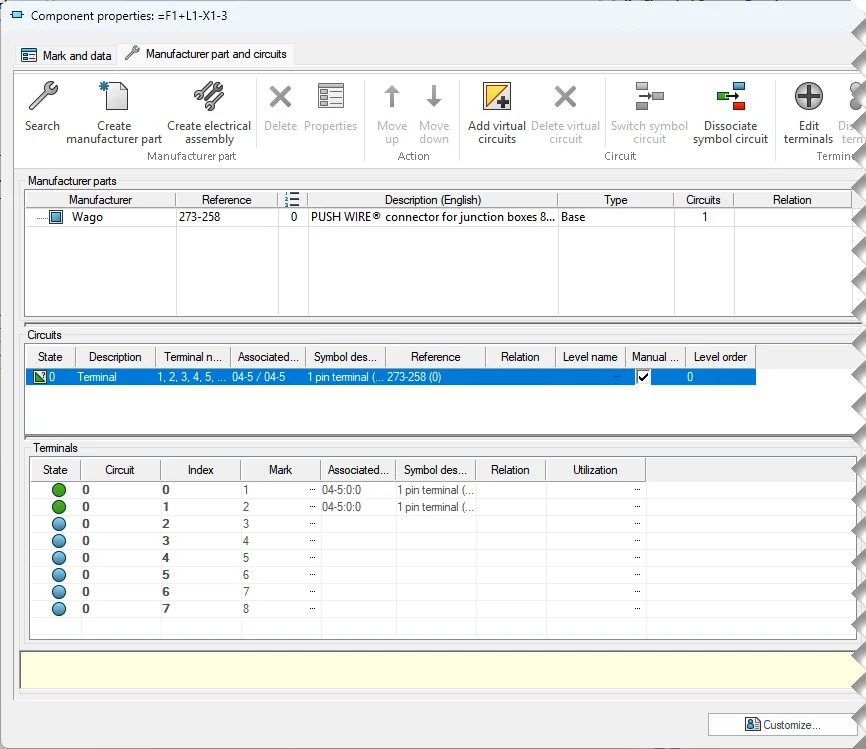
To show a more accurate mapping between the symbol and the part, the view is no longer limited to the part circuit and the symbol circuit. It now goes down to part pin and symbol pin.
A new list in the component properties shows the detailed characteristics of the pins, including the symbols they are associated with. It sits in a new Terminals group, right after the Circuits group, with columns for Circuit, Index, Mark and Relation.
The Distribute terminal command
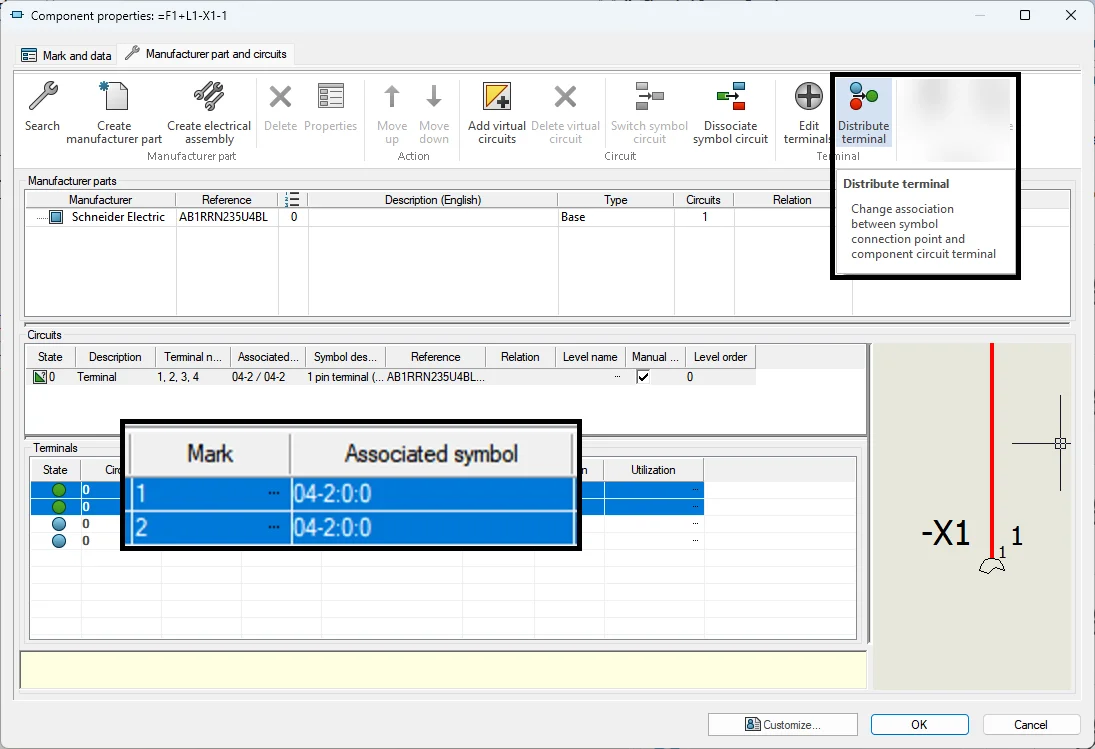
A new command, Distribute terminal, lets you change the mapping between symbol connection points and component circuit terminals after insertion. It is enabled when two terminals are selected. With it, you can dispatch the pins in the way that best suits the job, making cabling easier and documentation easier to read.
The same thing in the Terminal Strip Editor
The Terminal Strip Editor is where most people review and finish a strip, so it made sense to bring the same logic there.
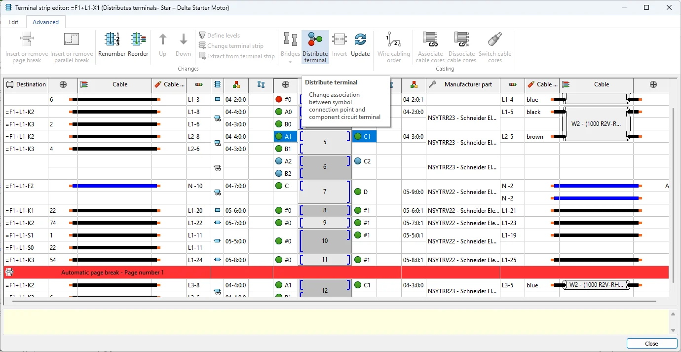
The Distribute Terminals command is now available directly from the Advanced tab of the Terminal Strip Editor and from the contextual menu. It behaves the same way as in Component Properties and the Edit Terminals dialog, so you can spread the terminals of a circuit in fewer steps. The contextual menu also has a Go to option to jump straight to a symbol, and the cross-reference columns now show the symbol circuit and point numbers.
On top of that, two new columns have been added, one on each side of the Mark column, to indicate the left and right connection points (terminals). Each one has a color status indicator (blue, red, green or yellow) next to the terminal mark, so the state of every connection is easy to read even on a busy strip.
Why it matters
For anyone working on control panels, special machines or larger junction blocks, this removes a long-standing constraint. You decide where the connection points appear, instead of the symbol deciding for you. That keeps the busy terminal blocks readable and the drawing closer to how the panel is actually wired.