
This SOLIDWORKS tutorial demonstrated the use of the spline on surface and split line features through the creation of an Earth inspired model. The design process began with the intention of representing the Earth in a more meaningful way. Initially, a decal was considered for the landmasses, but the concept evolved into a glass globe to emphasize the planet’s fragility. This shift led to exploring the spline on surface tool for the first time, revealing just how powerful and flexible it could be.
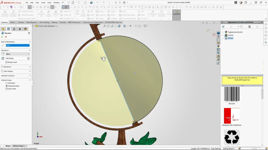
The process started with a plant pot model that had been previously created in the 3DEXPERIENCE app xShape. With this part open, a sketch was created on the front plane. Using the line tool, a line was drawn from the centre of the globes prongs, to the opposite side, followed by the use of a line arc to form a semi-circle. This profile was then revolved to create a spherical body, making sure the result remained unmerged.
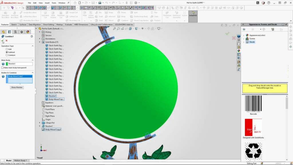
To integrate the plant pot into the globe design, the move/copy bodies feature was used to create a duplicate of the plant pot. The combine feature was then applied, setting the operation type to subtract. The globe was selected as the main body, and the copied plant pot body was chosen from the solid bodies list. Once applied, this created indents in the globe, allowing it to sit and rotate on its axis.
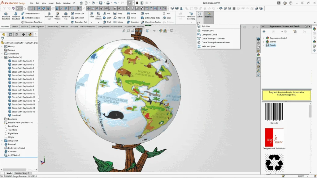
To preserve the original plant pot file, the part was saved as a new file named Earth Globe. From there, the globe’s surface was selected and the edit decal tool was used to import a world map PNG file. Within the mask image settings, the mask type was changed to selective colour mask, and the eyedropper tool was used to remove the pale blue background from the image. While not essential, this step simplified the mapping process by eliminating the image edges and allowing me to overlap the image without covering the map.
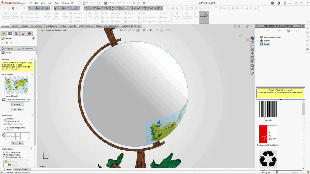
In the mapping settings, the software automatically applied spherical mapping. The decal placement was adjusted using the latitude and longitude controls, and the fixed aspect ratio option was unchecked to allow the image to be scaled appropriately across the globe. Further adjustments were made using the axis direction controls until the map aligned correctly. After confirming the positioning around the entire globe, the decal was applied.
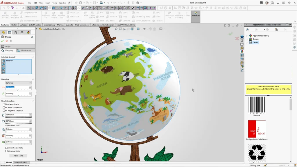
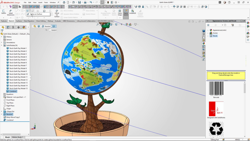
With the decal in place, the spline on surface tool was accessed from the sketch tab. This tool was used to trace the landmasses directly onto the globe’s surface. Although the initial decal lacked high detail, it provided a guide for demonstration purposes of this tutorial. More detailed references were used later, for the final design.
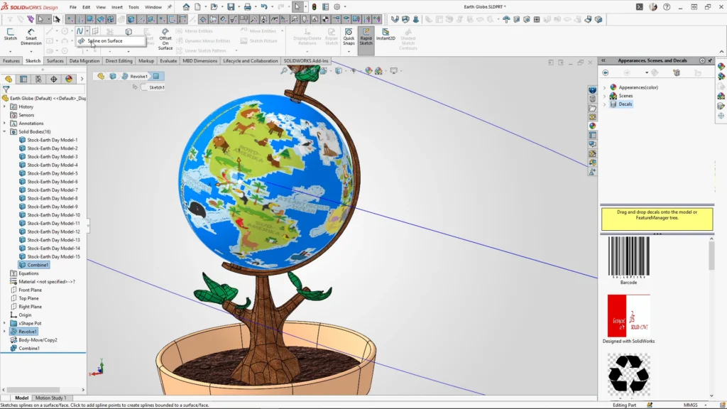
With the spline, I traced more slowly around complex edges, occasionally using escape on my keyboard, and restarting the spline tool to create sharper transitions. To keep the model more simple and stop the software slowing due to the complex sketches, the sketching was divided into three separate split sketches rather than attempting the entire globe in one go.
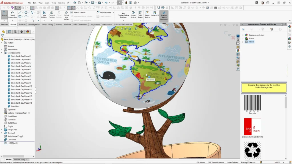
All sketches were completed before moving on to the split line feature, as applying it after one spline sketch would cause the decal to disappear. Using the split line tool with the split type set to Intersection, each sketch was selected along with the globe face. The surface split option was left as natural, and once applied, the globe’s surface became divided along the traced sketch.
For the final appearance, a green glass material was applied to the split land areas, while a blue glass appearance was used for the oceans, reinforcing the fragile, transparent aesthetic. The completed part file included all three sketches, forming a fully detailed globe. Once in Visualize, I added a frosted texture to the glass appearances, this stops the globe being too transparent and makes the map more clear.
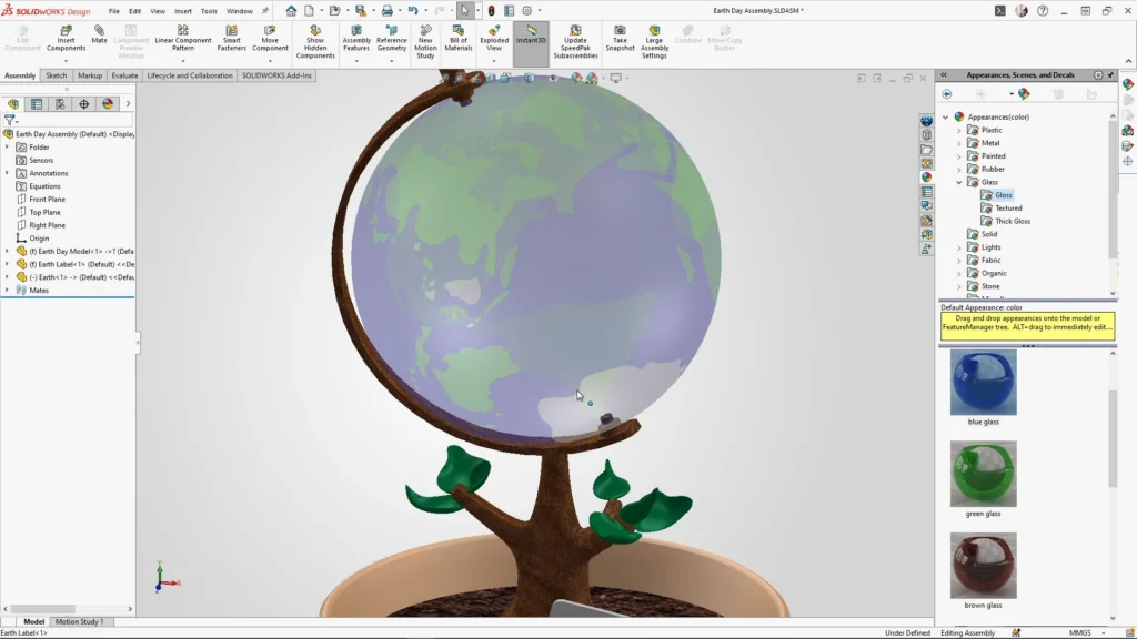
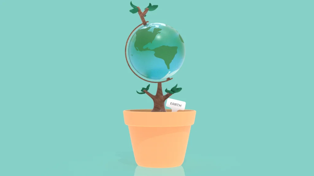
The save bodies feature was then used to export both the globe and the plant pot into an assembly. Within the assembly, the globe was mated in a way that allowed it to rotate freely on its axis. A small plant label was also included to complete the design labelled ‘Earth’. The final assembly was used to produce an animation, which was rendered using SOLIDWORKS Visualize, bringing the concept to life.
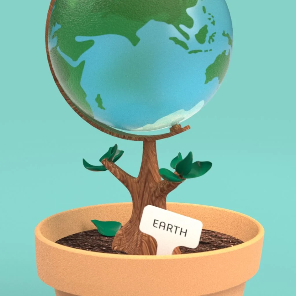
This project showcased not only the technical capabilities of tools like spline on surface and split line, but also how thoughtful design choices and material application could elevate a simple model into something more expressive and meaningful.