
In engineering, the gap between concept and physical reality is where most ideas fail. Geometry must become structure. Materials must behave as expected, and fabrication constraints impose limits that digital concepts alone cannot resolve.

For Carlos Reyes, an electromechanical engineer and SOLIDWORKS® content creator known as Carlos3D, this gap is the work itself. His projects are inspired by fictional objects in popular culture, which all require more than creativity. They demand disciplined modeling, iterative validation, and a willingness to confront physical constraints early in the design process. As Reyes explains, “What starts in my head becomes real. SOLIDWORKS is the tool I use to express that.”
Designing for Scale, Structure, and Reality
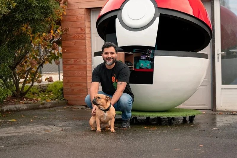
Reyes’ projects begin with open-ended questions that quickly become engineering problems. A sphere large enough for a person to fit inside introduces spatial constraints, structural requirements, and material trade-offs. Even seemingly simple geometry becomes complex at scale.
A spherical structure inspired by the Poké Ball required segmentation into repeatable components, each with consistent curvature and alignment. Early assumptions about materials proved insufficient. For example, wood’s flexibility required additional supports, while the structure covering exposed limitations in achieving a smooth surface.
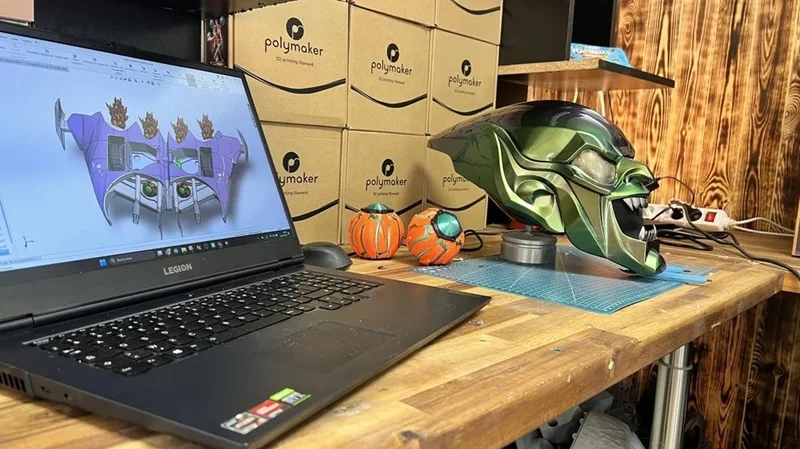
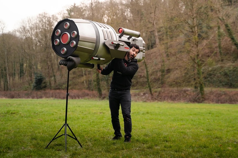
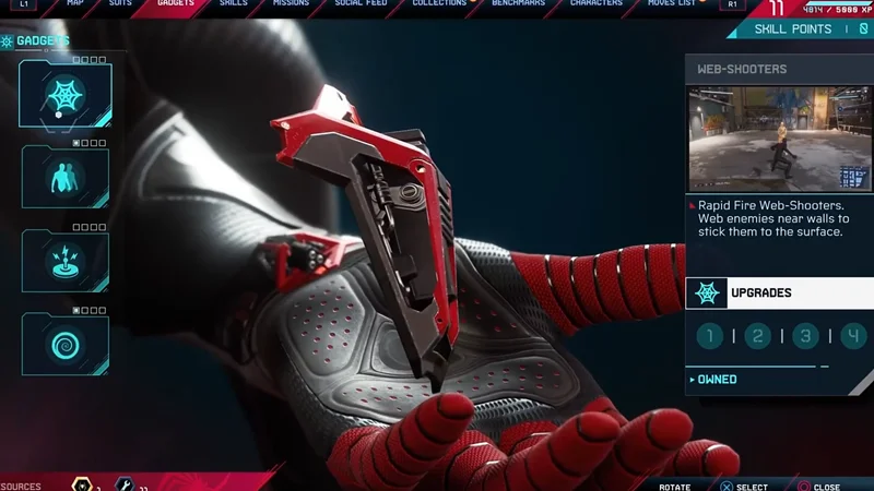
For a re-creation of a villain glider inspired by Spider-Man’s nemesis, the challenge was translating a stylized object into a manufacturable design, defining curves, edges, and proportions that preserved the visual intent. Both projects required continuous reconciliation between design intent and physical feasibility.
Modeling, Iteration, and Fabrication Alignment
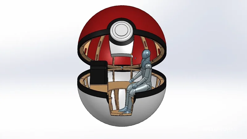
Reyes used SOLIDWORKS Design as the central environment for defining geometry, testing concepts, and preparing for fabrication. For the ball project, he modeled repeatable curved segments—referred to as banana shapes—that could be patterned around a central axis to form a spherical frame. Once validated in SOLIDWORKS, the structure was mirrored to complete the geometry.
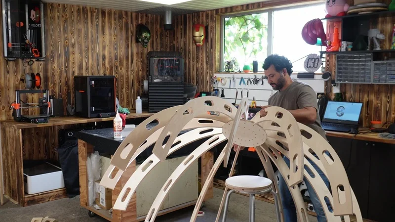
This approach allowed Reyes to move from a conceptual shape to a structured assembly that could be fabricated using CNC cutting. Pre-scale validation using laser-cut models revealed critical issues early, including insufficient space inside the Ball project and the need for intermediate supports. These insights informed revisions before full-scale production.
Fabrication workflows for the Ball project were directly driven by the digital model. CNC cutting produced the primary wooden structure, while assembly relied on controlled spacing. “I used wood glue and stainless-steel screws, plus some guides to keep the spacing consistent,” note Reyes. When traditional covering approaches failed to achieve the required surface quality, Reyes adapted by designing a segmented 3D-printed shell.
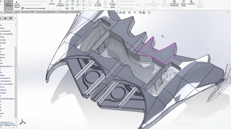
The villain glider project followed a similar pattern. Initial forms were created and refined digitally, enabling Reyes to sculpt complex surfaces and then translate them into printable components. He describes how he “quickly sculpted the glider’s initial form” in xShape and refined details in xDesign to move “from concept to first prototype.”

Iteration was continuous throughout both projects: Modeling informed fabrication, and fabrication constraints informed further modeling.
Execution Through Iteration and Control
The primary benefit of this approach is control over geometry, fabrication, and outcomes. By structuring designs in SOLIDWORKS before fabrication, Reyes identified issues such as material behavior, fit, and spatial limitations early in the process.
Iterative prototyping reduced downstream rework. Laser-cut models exposed design flaws before CNC production. Assembly feedback informed adjustments to tolerances and structure. When initial covering strategies failed, the existing digital model enabled a rapid pivot to a 3D-printed solution without redesigning from scratch.
The ability to break large assemblies into manufacturable components supported multi-process fabrication. CNC cutting, laser cutting, and 3D printing were coordinated from a single design source, maintaining alignment across processes.
Reyes describes his approach as, “Sometimes I break the rules. That’s important. Pushing design forward often means moving faces, deleting features, and trying things that aren’t standard.” This reflects a workflow grounded not in rigid process, but in controlled iteration.
Creative Designs That Are Manufacturable
Engineering creative concepts into physical reality requires masterful project management in how tools are used. In Reyes’ work, SOLIDWORKS Design functions as a structured environment for exploration, where ideas are tested against material, geometry, and fabrication constraints before they are built.
The result is not just visually compelling projects, but manufacturable, assembled systems that hold together under real-world conditions. That distinction is important in maker-driven engineering, where creativity and execution must coexist.
In any industry where concepts must become physical products, the ability to iterate, validate, and build with precision remains fundamental. Contact your local reseller to learn more about how SOLIDWORKS Design can help you get your products to market faster and more efficiently.
Check out this video to see Carlos and hear about how he creates his designs with SOLIDWORKS Design.