
Working in SOLIDWORKS assemblies can involve many very repetitive, mundane tasks. While some assembly features, such as Large Design Review and Performance Evaluation, often get the spotlight, a host of subtle quality-of-life tools—sometimes referred to as “delighters”—can eliminate repetitive clicks and keep your focus on the model.
I recently found myself performing a significant amount of assembly work in SOLIDWORKS. I’ve always wanted to design a CNC router, and when the opportunity came up to produce a new fileset for an upcoming training course at SolidProfessor, I decided to use it as an excuse to create a proof-of-concept model complete with stepper motors, hardware and bearings.
Through the process, I discovered (and rediscovered) several key enhancements added over the years, and alternative assembly workflows that I wish I had known from the jump, and would like to present them to you over various examples.
Feature Tree Navigation
As assemblies grow in complexity, the FeatureManager design tree quickly becomes an overwhelming, nested hierarchy, making it difficult to locate a specific component without endless scrolling. Practicing tree navigation shortcuts and filtering tools prevents you from losing your place in deep assemblies.
Breadcrumbs
Breadcrumbs significantly aid SOLIDWORKS Feature Tree navigation by displaying a contextual hierarchy directly at your cursor when you click any geometric entity in the graphics area.
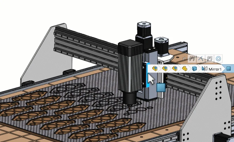
Figure 1. Using Breadcrumbs to navigate the Feature Tree.
Pressing the default hotkey D brings the breadcrumb trail straight to your mouse pointer. This allows you to edit mates, open parent sub-assemblies, or inspect sketches without moving your cursor back to the tree. But perhaps the biggest benefit is that you are only shown information related to the components that are selected, reducing the chances of being distracted by extraneous information or erroneously choosing an item from the wrong assembly.
Collapse All Items
Expanded sub-assembly branches quickly clutter the FeatureManager. Right-clicking the top of the feature tree provides access to the command Collapse Items, which can also be activated by the Shift + C keyboard shortcut. This collapses all expanded nodes across the entire tree back to the top level in a single keystroke.
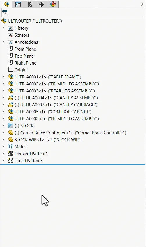
Figure 2. Collapse Items (Keyboard shortcut Shift + C).
Feature Tree Filter
The filter at the top of the tree isolates components by part name, custom property or description. You can also configure it to hide non-matching items in the viewport, letting you isolate results graphically.
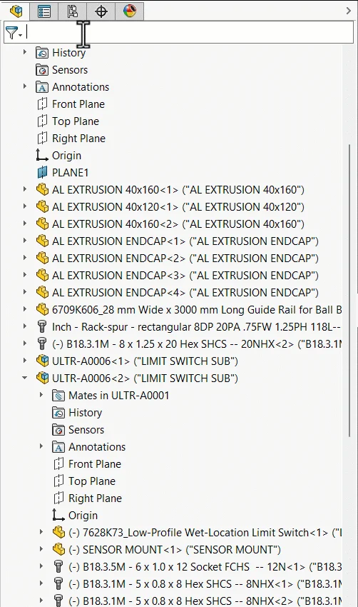
Figure 3. Filtering the Feature Tree.
Display Pane
The display pane is an expandable menu on the side of the feature tree that allows quickly hiding and showing various parts, planes or sketches.
Expanding the chevron on the right edge of the FeatureManager exposes a column-based grid for rapid visualization control. You can toggle component visibility, change display modes (wireframe/shaded), assign appearances and apply transparency.
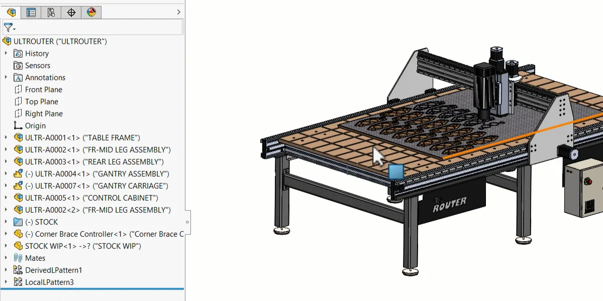
Figure 4. Using the Display Pane.
Note: I struggled with whether to place this under the “Feature Tree” section or Viewport Navigation in general, as it’s very useful for both! It’s a tool I use daily and many users seem to be unfamiliar with.
Mates
Mating is central to assembly work in SOLIDWORKS, and anything you can do to improve model robustness or save time will go appreciated by both you and your colleagues who need to interact with your assemblies.
Width Mates & the “Free” Constraint
The Width mate eliminates the need to create mid-planes or calculate offset dimensions to center a component between two faces. By selecting two “Width” reference faces and two “Tab” reference faces, SOLIDWORKS dynamically constrains the geometry.
Beyond simple centering, the Free constraint option is particularly powerful for dynamic mechanisms. It restricts a component within the boundary limits of two opposing faces while allowing it to slide freely between them along the unconstrained axis- shown in this case for restricting motion along a dovetail slide.
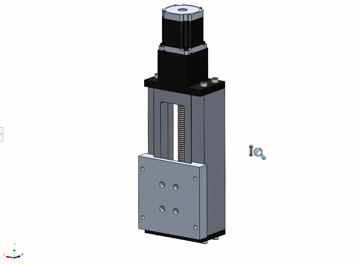
Figure 5, Width Mates with Free Limit.
Note: the Width mate, despite being an advanced mate, can also be added using QuickMates- simply holding down the CTRL key on the keyboard and selecting 4 faces. SOLIDWORKS will do its best to automatically sort out the pairs of width selections into the correct order, and it is surprisingly reliable.
Pattern-Driven Component Pattern
Manually patterning fasteners or brackets by typing in instance counts and spacing dimensions creates duplicate work that breaks when the underlying part changes. The Pattern-Driven Component Pattern (also known as a Derived Pattern) references existing feature patterns, such as Linear Patterns, directly from your parts.
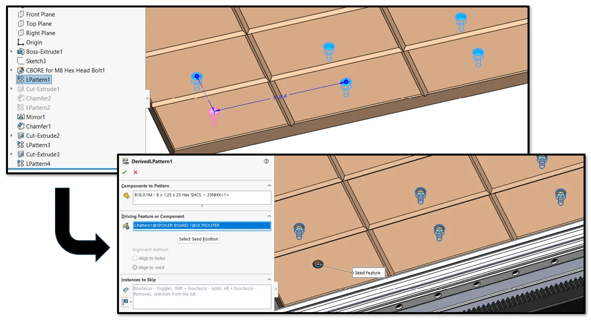
Figure 6. Part-level Linear Pattern (above) and Assembly-level Derived Pattern (below).
When the pitch, spacing or instance count of the source feature changes in the part model, the assembly hardware pattern updates automatically. This preserves design intent and prevents downstream Bill of Materials errors caused by out-of-sync fastener counts. It’s an incredibly powerful and under-utilized feature.
Make First Selection Transparent
When mating components inside enclosed assemblies or tight housings, the first part you select often blocks your line of sight to the mating geometry behind it. Instead of manually hiding components, sectioning the model or toggling display states, SOLIDWORKS includes the “Make first selection transparent” option directly within the Mate PropertyManager.
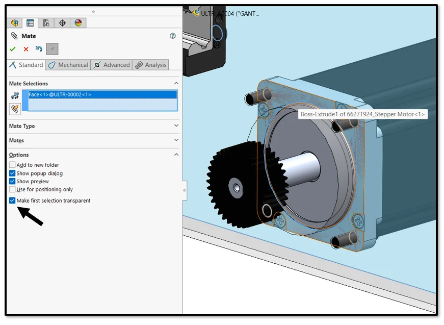
Figure 7. Mate Settings – Make First Selection Transparent.
When this option is enabled, selecting the first entity automatically turns that entire component semi-transparent in the viewport. This immediately exposes the internal faces and reference geometry of the adjacent part, allowing you to make your second mate selection directly through the first component. Once both selections are made, the component automatically returns to its original display.
I can’t emphasize enough how much I found myself enjoying this option as I worked through my assembly work, and it had me for the first time in years using the Mate feature “the old-fashioned way” rather than just holding CTRL, pre-selecting faces, and utilizing QuickMates for the majority of my mating work. No longer do we have to drag components far away so that we have enough space between them to select otherwise occluded pairs of faces!
Viewport Navigation & Ergonomics
Repetitive cursor travel and constant viewport manipulation are some of the primary sources of CAD fatigue during long modeling sessions. Optimizing how you interact with your 3D viewport preserves your visual context and can reduce hundreds or thousands of unnecessary clicks and mouse movements per day.
Open Part in Position
Opening a component from an assembly normally loads the part at its default origin orientation, which requires you to rotate the model to inspect the specific face you were just examining in the assembly.
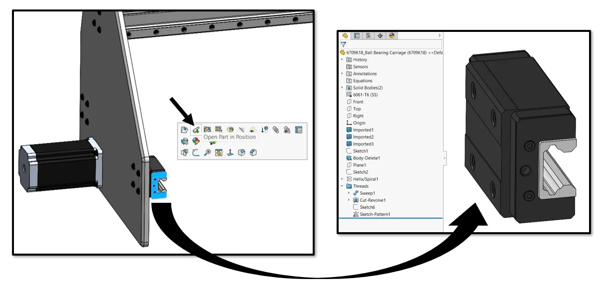
Figure 8. Open Part in Position.
Using Open Part in Position (available on the component context menu) preserves the exact camera angle, zoom level and display orientation from your active assembly viewport. When the part opens in its own window, the specific face or feature of interest remains directly in front of you, allowing you to keep your bearings.
Saved (Named) Views
When working in complex assemblies, finding the exact camera angle to check a tight clearance can take significant rotation and zooming. Pressing the Spacebar opens the View Orientation menu, allowing you to save your current camera angle as a New Named View. Instead of repeatedly repositioning the model, you can instantly snap back to dedicated angles and zoom levels. This is also very useful for taking repeatable screenshots of your model.
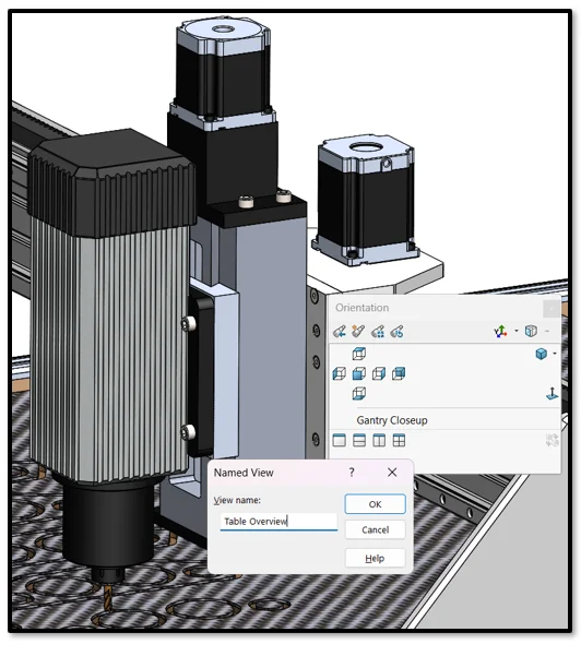
Figure 9. Creating Saved (Named) Views.
3D Mouse (SpaceMouse) Navigation
3D mice for SOLIDWORKS seem to be a polarizing option, where some users swear by them and cannot live without them, and others don’t get the hype. I personally think this discrepancy comes down to two things: your use case, and willingness to get over the initial learning curve.
For sketching, modeling simple parts and drafting drawings I think the 3D mouse, while useful, is largely unnecessary. For assembly work, design reviews and model preparation for other software or add-ins, I find the 3D mouse indispensable. After a couple days of acclimating to it, it’s really hard to go back to mouse-based rotation, panning and zooming.
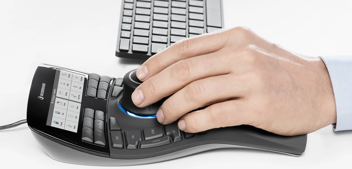
Figure 10. 3D Mouse Navigation.
The ergonomics of using a 3D mouse in one hand and your traditional mouse in the other are also hard to overstate. The higher-end 3D mice have mappable shortcut keys that mean for common assembly tasks, I hardly ever have to reach the keyboard, allowing me to get into a flow state for mating, inserting or suppressing components, etc.
I’m so dependent on these now that I have a SpaceMouse Enterprise for my main setup, and a SpaceMouse Wireless for doing on-the-go work!
Not having to hold down a button for rotation also reduces tremendous strain on your primary hand, and enhances the precision of my selections when I can focus on just selecting things with the traditional mouse.
Wrist Rests / Supports
Even with all the shortcuts we’ve discussed so far, if you’re doing assembly or other CAD work day in and day out, making many thousands of clicks per day, you risk repetitive strain injury (RSI).
For SOLIDWORKS use, I use a gliding wrist support (such as the DeltaHub Carpio 2.0), which greatly reduces the perceived stress on my wrist when clicking and scrolling and is easy to take on the go. I’ve recommended these to several friends and colleagues. Although it takes a day or two to get used to the gliding wrist support, the payoff is enormous once you’ve adjusted to it. It’s a world of ergonomic improvement and doesn’t slow your workflow or negatively affect mouse precision.
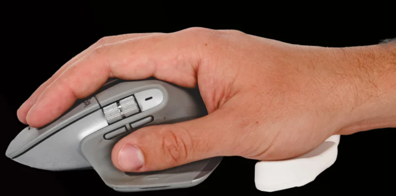
Figure 11. Gliding Wrist Rest for Mouse Support.
If it’s not your thing, you could still keep a more conventional wrist-brace on hand for those especially click-heavy days.
Fasteners & Hardware
Fasteners typically represent the highest component count in any mechanical assembly, making manual insertion and sizing a major source of modeling friction. Efficiencies gained with fasteners and hardware can have a compounding effect across your project.
SOLIDWORKS Toolbox
For standard fastener libraries, SOLIDWORKS Toolbox automates the insertion and sizing of screws, nuts, washers and retaining rings.
Dragging a Toolbox fastener directly onto a Hole Wizard hole triggers automatic sizing, matching the fastener thread, length and clearance to the hole definition. In addition, features like Auto-size to mated geometry automatically adjust screw engagement depths based on the thickness of the stacked assembly components.
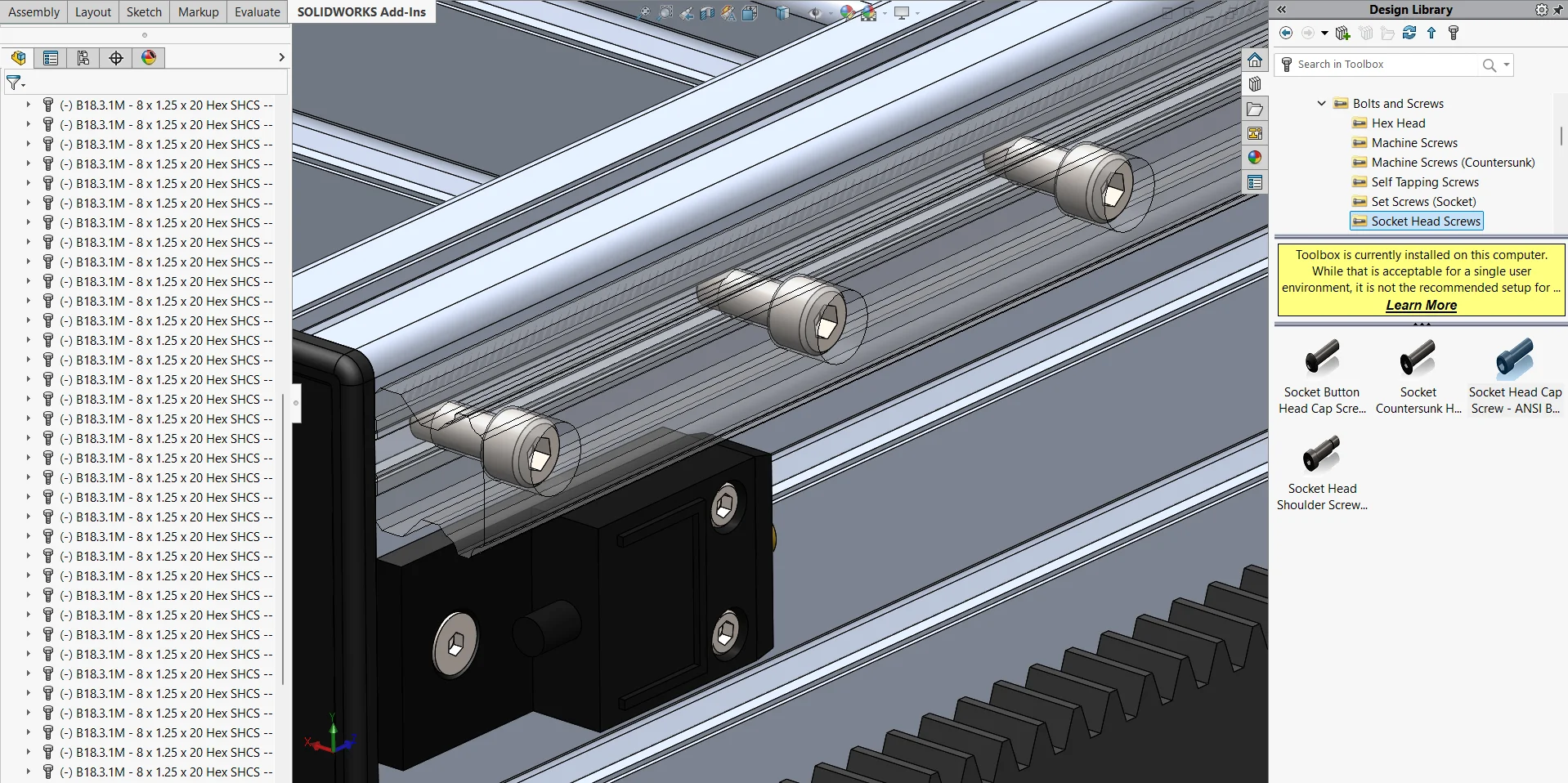
Figure 12. SOLIDWORKS Toolbox Add-in.
McMaster-Carr Add-In
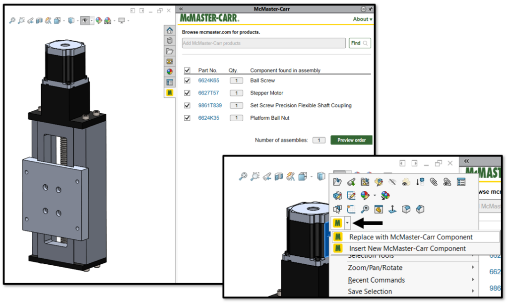
While the Toolbox add-in does a good job handling standard ANSI/ISO fasteners, purchasing off-the-shelf hardware, motors and other components benefits from vendor-accurate geometry. The McMaster-Carr Add-In embeds its extensive parts catalog directly inside the SOLIDWORKS task pane.
You can browse product specifications, locate the exact catalog part number and insert native 3D models directly into your assembly viewport easily—bypassing the manual steps of downloading, extracting and saving neutral CAD files from a web browser.
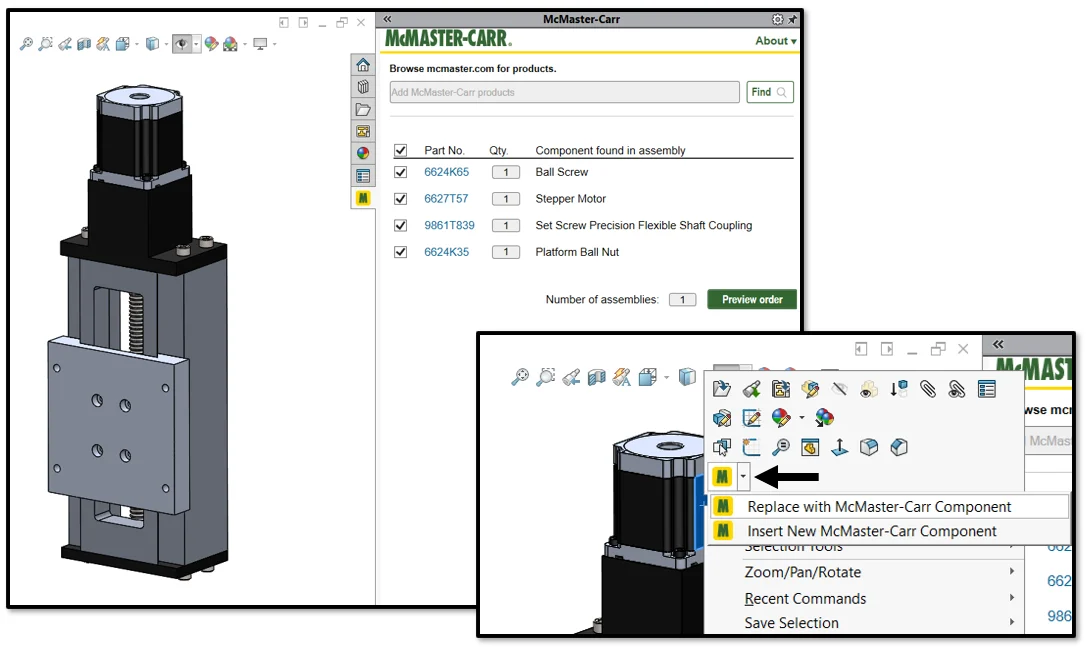
Figure 13. McMaster-Carr SOLIDWORKS Add-in with Integrated BOM / Shopping Cart.
Moreover, some of my favorite features of the McMaster-Carr add-in are that it dynamically builds a BOM/Shopping Cart for you, so if you are ready to produce your project or prototype, you can easily place an order. And if you need to swap a component, like realizing that the stepper motor I selected was a little undersized, I can easily use the command “Replace with McMaster-Carr Component,” which will throw me back to the catalog page to choose the next size up.
Conclusion
Incorporating these small tools and shortcuts into your assembly workflow can help reduce design friction and prevent modeling errors. I learned these tips “the hard way” after hours of assembly modeling. I hope you can learn from my struggles and benefit from them for your next project! I continue to be impressed by both the quality-of-life and performance improvements SOLIDWORKS makes with its assembly environment, which seems to be one of the last bastions of heavy feature development for the otherwise mature CAD tool.
I remain curious to see how future enhancements related to AI (like the LEO and AURA virtual assistants) will further improve our day-to-day work with the assembly environment.