
In many engineering projects, designers work with imported CAD files such as STEP and IGES received from suppliers, customers or existing products. These files are usually assembly or part models created for manufacturing or reference purposes, not for easy editing.
When imported into SOLIDWORKS, the models normally appear as solid bodies without sketches, features or design history. Because of this, editing them with traditional modeling methods can be difficult.
In this blog, we will use an imported STEP file of a Renishaw Optical Tool Setter (OTS), a CNC machine accessory used for tool measurement and calibration. This example illustrates how Direct Editing tools can modify imported geometry quickly and easily.
With Direct Editing tools in SOLIDWORKS, engineers can remove faces, move geometry, split bodies, combine bodies and update dimensions without rebuilding the entire model from scratch. This makes imported STEP and IGES files much easier to work with in real engineering projects.
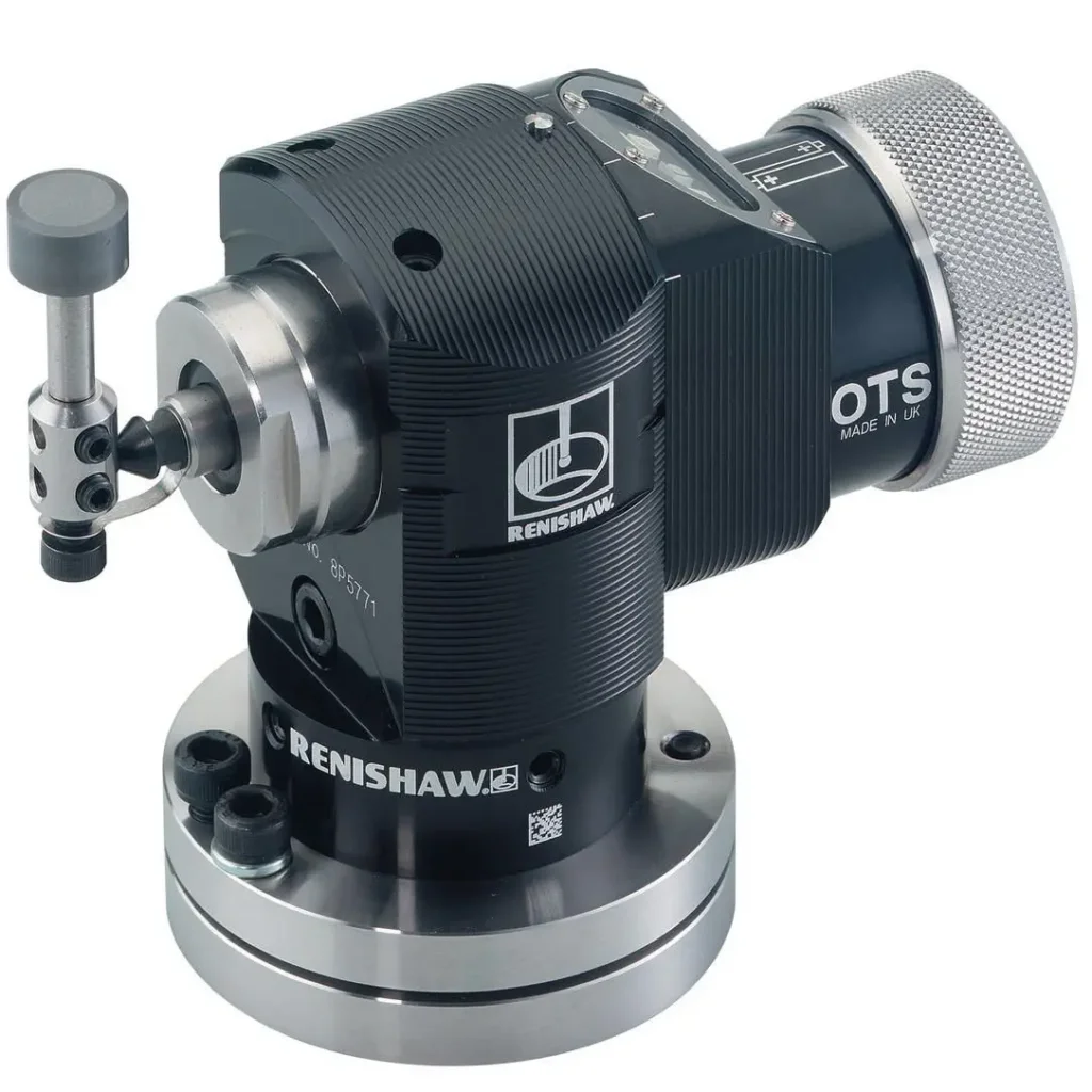
Figure 1. Renishaw OTS Optical Tool Setter reference model. (Source: Renishaw.)
Working with Imported STEP Files
When you open a STEP file, SOLIDWORKS converts it into a solid body. However, the model is “dumb geometry,” meaning:
- No sketches
- No features
- No design intent
Even though it looks complete, it is not easy to edit using traditional modeling methods. Instead, SOLIDWORKS provides tools to directly modify faces and bodies.
What Is 3DInterconnect in SOLIDWORKS?
3DInterconnect is a utility in SOLIDWORKS that lets you open third-party CAD files in their native format without converting them to SOLIDWORKS files first. This helps reduce translation issues that can occur during file conversion.
By default, 3DInterconnect is enabled, but it can be turned on or off from System Options > Import.
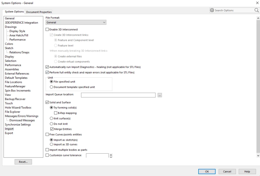
Figure 2. Location of the 3DInterconnect Import option in SOLIDWORKS.
When enabled, SOLIDWORKS maintains a live reference to the original CAD file, allowing changes made in the source CAD system to update automatically inside SOLIDWORKS. If needed, this link can also be broken to prevent unintended external updates.
When disabled, the file is imported as a standalone SOLIDWORKS body using the traditional import workflow, with no external reference to the original CAD file.
This functionality is supported for formats such as STEP, ACIS and IGES. Parasolid files do not require 3DInterconnect because they are already fully compatible with SOLIDWORKS and do not require translation.
Before working with imported geometry, it is important to understand the difference between enabling and disabling 3DInterconnect. The comparison below highlights how each option affects imported geometry, file references and update behavior in SOLIDWORKS.
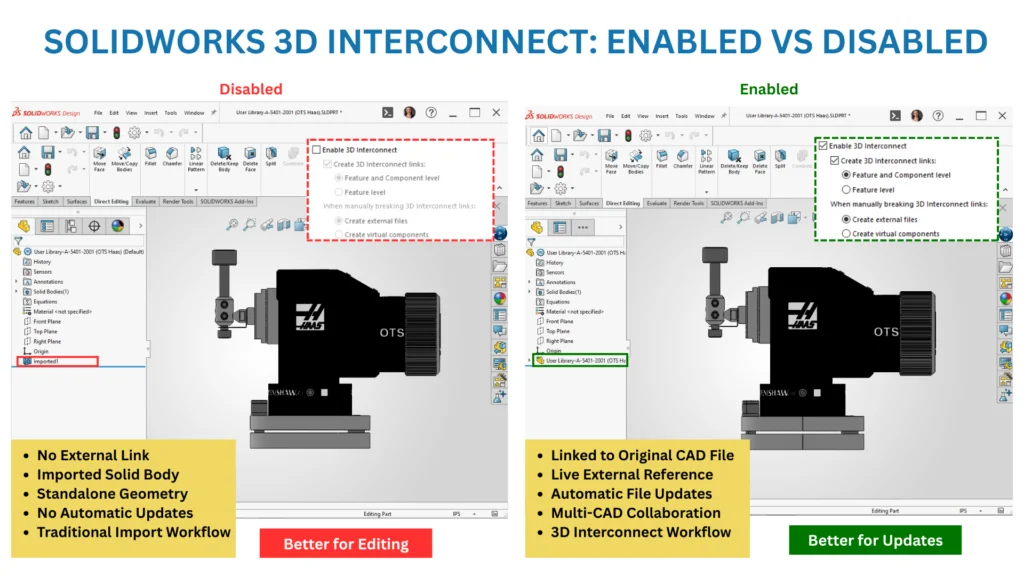
Figure 3. 3DInterconnect enabled vs disabled in SOLIDWORKS.
If 3DInterconnect is disabled, geometry translation errors may occasionally appear, even when the original model is valid in the source CAD system. These issues are commonly caused by differences in unit precision between CAD systems or limitations in how certain geometry types are represented, such as splines versus arcs.
Understanding how to analyze and repair imported geometry is essential when working with transferred CAD files. This is where Import Diagnostics becomes especially useful.
Direct Editing in SOLIDWORKS
Once the model is imported, Direct Editing tools can be used to modify geometry without relying on sketches or feature history.
These tools are available in the Direct Editing Command Manager, which can be activated by right-clicking on the Command Manager tabs and enabling “Direct Editing.”
This toolbar provides a set of fast and practical editing functions specifically designed for working with imported geometry such as STEP files, allowing engineers to make quick design modifications without rebuilding the model.
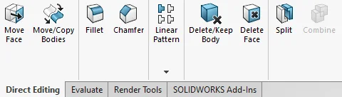
Figure 4. Direct Editing in SOLIDWORKS.
Main Direct Editing Tools
Move Face
The Move Face tool is used to push, pull, translate or rotate selected faces directly on the model. It is commonly used to reposition holes, adjust wall thickness or modify functional geometry without rebuilding features.
Delete Face
The Delete Face tool removes selected faces from the model while automatically healing surrounding geometry. It is often used to remove fillets, chamfers, holes, or unnecessary details from imported STEP files.
Move/Copy Bodies
The Move/Copy Bodies tool allows entire solid bodies to be moved, rotated, or duplicated. It is useful for repositioning imported geometry and working with multi-body STEP models.
Split
The Split tool divides a solid body into multiple separate bodies using a plane, surface, or sketch. This helps isolate regions of the model before applying further modifications.
Combine
The Combine tool merges multiple solid bodies into a single solid body. It is commonly used after Split or Move/Copy Bodies operations to rebuild the model as one continuous part.
Delete/Keep Body
The Delete/Keep Body tool is used to remove or retain selected solid bodies in a multi-body part. It is especially useful when working with imported STEP files that contain multiple bodies. This tool helps simplify the model by deleting unnecessary geometry or isolating only the required bodies for further editing.
Practical Editing Workflow (STEP by STEP)
After importing the Renishaw OTS Optical Tool Setter STEP file, the model appears as a single solid body without feature history. At this stage, no design intent is available, so modifications must be done using direct geometry editing.
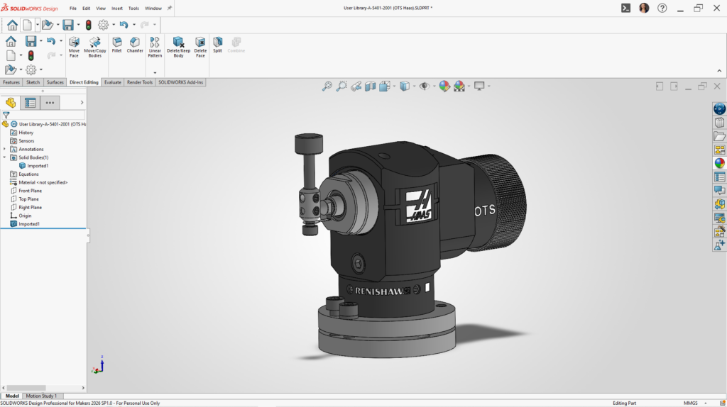
Figure 5. Imported Renishaw OTS STEP model before editing.
1. Run Import Diagnostics (Always the First Step)
After importing the Renishaw OTS Optical Tool Setter STEP file, the next step is to verify the quality of the geometry using Import Diagnostics.
This tool is used to detect and repair faulty faces, gaps or inconsistent surface data in imported models. In this case, the analysis confirms that the geometry is clean, with no errors detected.
This step is important because it ensures that the model is fully stable before applying any direct editing operations, such as Move Face or Delete Face.
Even when no issues are found, running Import Diagnostics is considered an engineering best practice, as it validates that the imported data is reliable and ready for modification.
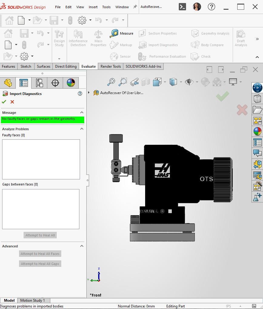
Figure 6. Clean imported geometry confirmed by Import Diagnostics.
2. First Modification → Delete Face
In this step, I used the Delete Face tool to remove existing chamfers from the imported Renishaw OTS model.
The selected chamfers (1.4 mm at the top and 2.0 mm at the end of the coupler part) were removed, and the chamfer size was modified to 1.5 mm. This is a common step when working with STEP files, because imported models often include manufacturing features that may need to be updated during design editing.
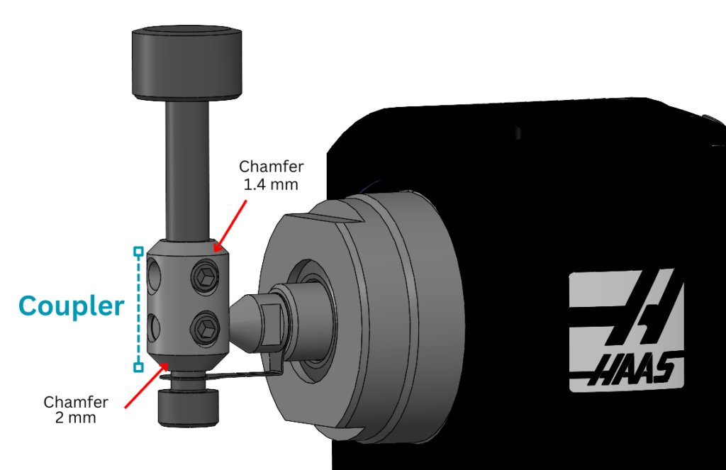
Figure 7. Original chamfer geometry before modification.
When I applied the Delete Face tool, SOLIDWORKS automatically healed the surface, keeping the model solid and closed.
If the model does not heal properly or a gap is left, use the Delete and Patch options. This removes the face and fills the missing area with a smooth surface, keeping the model clean and continuous.
After removing the original chamfers, I created new chamfers on both locations with a modified value of 1.50 mm to meet the updated design requirements.
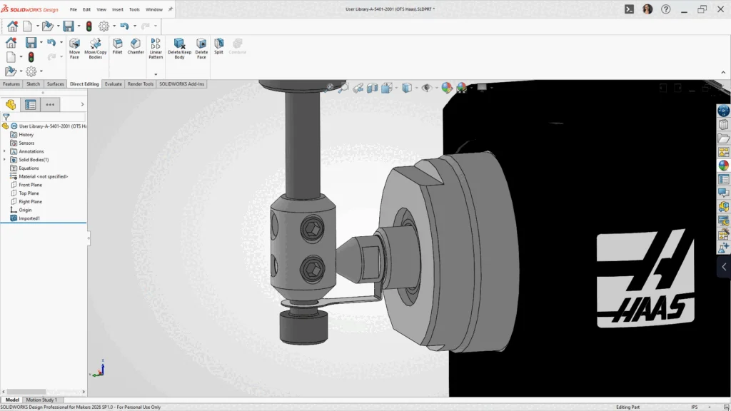
Figure 8. Using Delete Face to edit chamfers in an imported STEP model.
These tools helped me easily modify the imported geometry and update the feature before continuing with further design changes.
3. Modify Geometry → Move Face
Next, I used the Move Face tool to modify the functional geometry of the imported Renishaw OTS model.
In this example, I moved the hole position on the OTS model using the Move Face feature. First, I selected the cylindrical faces of the hole. Then, in the Direction Reference, I selected the Top Plane and applied a movement distance of 17.50 mm.
After confirming the operation, the hole was successfully moved to the new position while keeping the model solid and continuous.
This tool is very useful when editing imported STEP files because it allows quick geometry changes without rebuilding the entire feature.
4. Modify Geometry → Move/Copy Bodies, Split and Combine
Since the imported Renishaw OTS model was originally a single solid body, I first needed to split the model into separate bodies so the TOOL DATUM DISK could be rotated independently.
First, I created a reference plane using Reference Geometry → Plane. I selected the required face and created a coincident plane at the position where the model needed to be cut.
Next, I created an axis on the cylindrical surface. This axis would later be used as the rotation reference for the TOOL DATUM DISK after splitting the model.
After creating the plane and axis, I used the Split command. I selected the created plane as the trim tool and clicked Cut Part, which separated the imported model into two solid bodies.
Then, from the Direct Editing tab, I selected Move/Copy Bodies. I chose the TOOL DATUM DISK body and used the previously created axis as the rotation reference. This step is important because using the axis keeps the rotation centered correctly on the cylindrical geometry.
I then entered a rotation value of 90 degrees, and the TOOL DATUM DISK was successfully rotated to the new position.
Finally, if the separate bodies need to be reunited into a single part, the Combine command can be used. By selecting the two solid bodies and applying the Combine operation, SOLIDWORKS merges them into a single solid body.
Wrap up
Working with imported CAD files in SOLIDWORKS is much easier with Direct Editing tools. They let engineers modify geometry directly without feature history.
You can quickly remove faces, move geometry, adjust dimensions and clean up imported STEP files. This reduces redesign time, improves flexibility and makes it easier to modify supplier or customer models directly inside SOLIDWORKS.
Direct editing helps you update imported models more quickly and integrate them more easily into your design process.