
Note: this is Part Two of the Change Management with SOLIDWORKS series. If you missed part one, you can catch up here.
Change execution in SOLIDWORKS
Change Execution has both web and Desktop applications. It is an application that lets you manage change processes within your company. With Change Execution, you can create the following activities:
- New Investigation Request
- New Change Request
- New Change Action
Step-by-Step Implementation in 5 Steps
To ensure the application is clear, I will explain the entire process using a project study.
Scenario: It focuses on the first release and revision process for a company that manufactures brake discs. Throughout the scenario, I explain the process through the roles of Design Engineer and Lead Engineer.
Design Engineer (Ridvan Polat): The engineer responsible for brake disc design.
Lead Engineer (Hanen Bdioui Polat): Engineer responsible for the technical control of designs and Change processes.
Since I demonstrated the entire process in detail in the videos throughout the implementation steps, I included the engineering logic (Technical Insight) behind the videos to avoid repetition.
How is the First Release Process Handled in SOLIDWORKS Design?
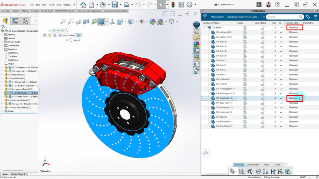
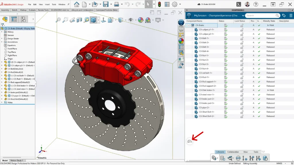
Apart from the Disc within the Brake Disc assembly, all parts have reached the Released Maturity state following the necessary checks. After the final operations I performed as the Design Engineer, all necessary design steps for the Disc part have also been completed. The Brake Disc assembly is now ready for production.
It is ready, but how will someone opening the assembly know that this is production-ready data? PLM provides the answer to this question. Product Lifecycle allows us to determine which cycle, that is, which maturity state, the data has reached. In this way, while allowing someone examining the data to obtain more detailed information about the product, it also secures the data against unintended changes.
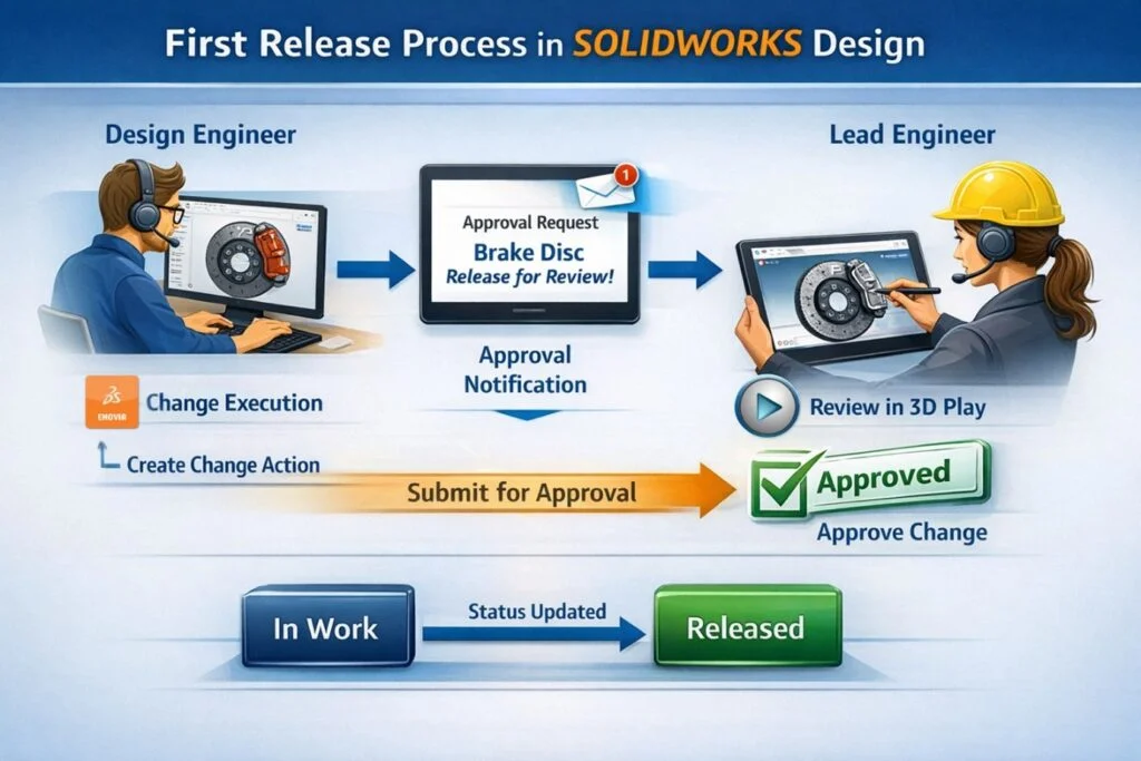
Most companies want to execute these processes in a controlled manner, subject to approval. For this purpose, the Change applications I mentioned at the beginning of the article are used. As the Design Engineer, I have completed the design and am initiating the First Release process by creating a Change Action to receive approval that the design is ready for production.
Workflow
Step 1: Initiating the First Release Process
While on the SOLIDWORKS screen, we can add components from the 3DEXPERIENCE window to the desired widget on the platform in the web browser using drag-and-drop. You can also open SOLIDWORKS data located on a Widget in SOLIDWORKS using drag and drop. This will make working with the platform easier when using dual screens.
I added only the assembly directly to the Proposed Change area, without adding both the part and the assembly. Only a single part remained within the assembly, and I want that part to be Released as well. To achieve this, while work under is active in Lifecycle, and just before submitting the CA for approval, I check the Include structural object box and perform the Freeze operation. With this action, all components under the assembly are automatically added to the realized Change area. This way, when the CA receives approval, both the assembly and the part will be Released.
Before submitting the CA for approval, components added to the Proposed Change area must be frozen using Lifecycle while work under is connected to the CA. If this action is not performed, you are not allowed to submit the CA for approval.
Step 2: Reviewing the Design and Giving Approval
To examine the components submitted for approval, you can inspect the assembly in the CA widget within the 3D Play Widget using drag-and-drop. You can use many review tools, such as exploding, sectioning and measuring, on any device through your browser, without opening SOLIDWORKS. This is a particularly good option for those in managerial positions who provide approval but do not use SOLIDWORKS.
With the Lead Engineer approving the CA, the Assembly and Part have been promoted from the In Work state to the Released state, receiving approval for production.

How is the Revision Process Handled in SOLIDWORKS Design?
Following tests performed on the disc that received production approval, a number of problems were encountered on the disc part. The team responsible for Production and Analysis provided the following feedback to the Lead Engineer:
- High hole density causes stress concentration and thermal cracking. Reduce hole count to improve structural integrity.
Discussing with the Production and Analysis team, the Lead Engineer stated that reducing the number of holes could create other problems and made the following suggestion:
- Integrate radial slots to compensate for reduced holes. This ensures gas evacuation and pad cleaning without structural weakness.
After the meeting, it was decided to proceed with a revision. The Lead Engineer wanted to create a document containing the Problem and solution suggestions, turn this into a task, and notify the Design Engineer. So, was she going to do this by sending screenshots or emails? Even if she did, how would she track it? How would the record of this work be kept for the future?
Here, the answer to all these problems lies in the application project.
Workflow
Step 1: Initiating the Development Process
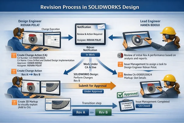
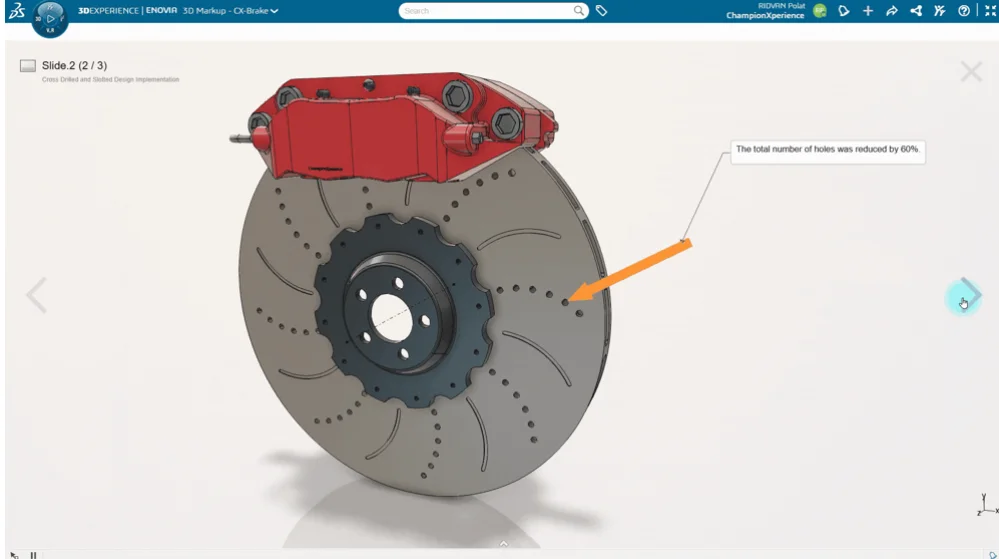
Instead of creating a document containing the problem and solution suggestions, the Lead Engineer used the 3D Markup widget. She presented both the problems and the suggested solutions directly on the Assembly.
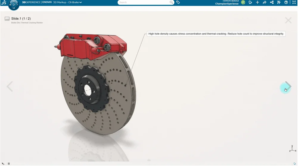
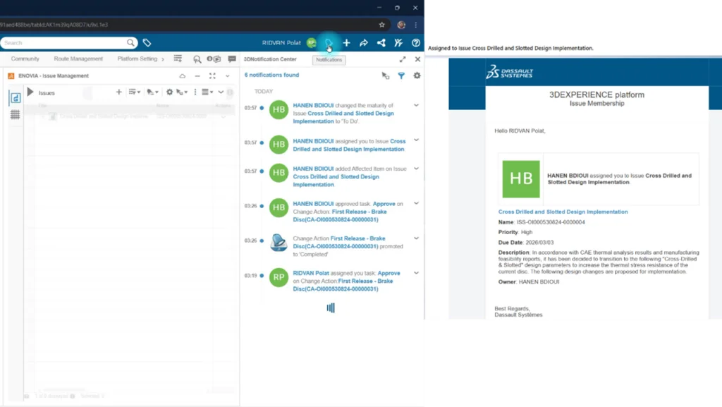
To notify the Design Engineer of this problem, the Lead Engineer used the Generate Issue feature located in 3D Markup and defined the problem as follows:
“In accordance with CAE thermal analysis results and manufacturing feasibility reports, it has been decided to transition to the following “Cross-Drilled & Slotted” design parameters to increase the thermal stress resistance of the current disc. The following design changes are proposed for implementation.”
For the solution to the problem, the Lead Engineer included the following steps in the Issue:
Solution Suggestion
1. HOLE REVISION
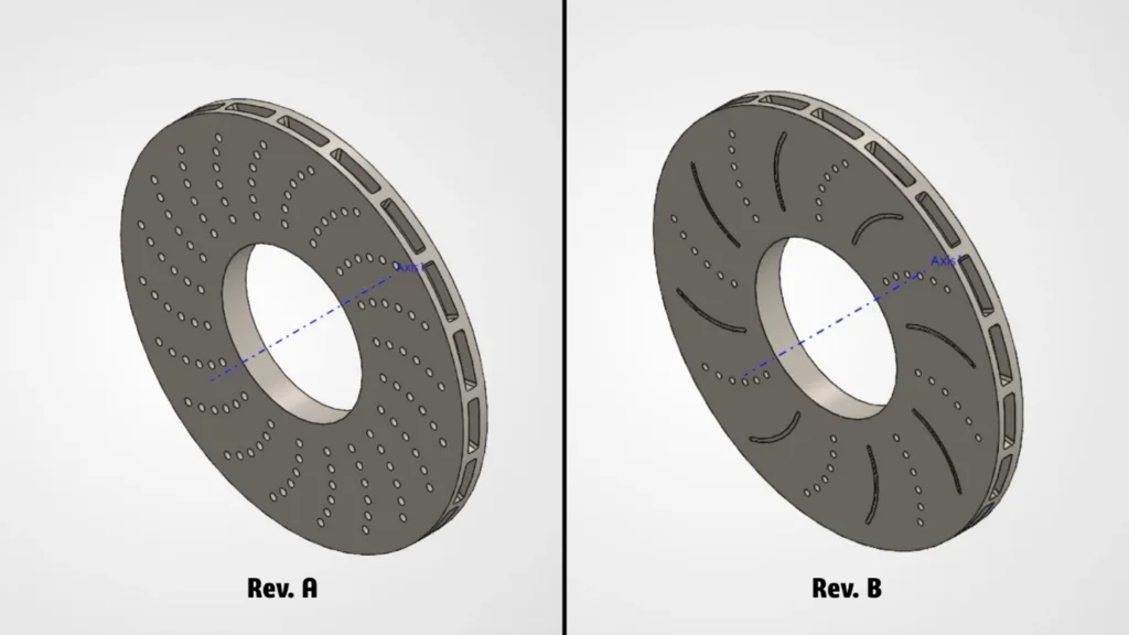
- Hole Count Reduction: The hole count shall be reduced by 60% to increase the thermal mass of the disc.
- Diameter Reduction: The hole diameter shall be reduced from Ø6 mm to Ø5 mm to decrease stress concentration.
2. SLOT INTEGRATION
- Curved slots shall be added between holes to compensate for the gas evacuation loss caused by hole reduction.
- Slot Width: 3.0 mm
- Slot Depth: 0.8 mm
Step 2: Initiating the Revision Process
The platform has a feature offering notifications both via the browser and via email.
Issue Management also has a maturity state. As the Design Engineer, by promoting the maturity state from To Do to In Work, I informed the Lead Engineer that I had started the task and was working on it.
Just like in the First Release process, revision processes are also executed with Change Action. In this way, revision creation can be managed in a controlled manner.
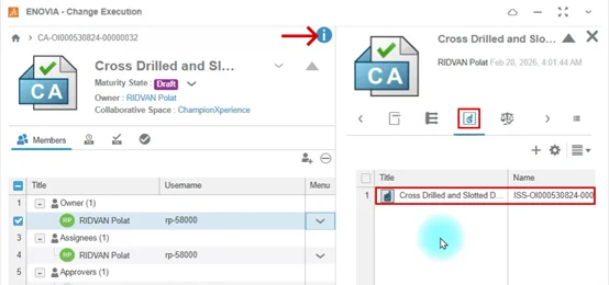
It is possible to establish a connection between the CA and the Issue. Thanks to this, CA maturity changes directly trigger the maturity changes of the Issue.
An improvement needs to be made on the Disc. Since the Disc is the most critical part of the assembly it is in, it directly affects the assembly. That’s why I multi-selected the Disc Part and the assembly on the SOLIDWORKS screen and dragged and dropped them into the Proposed Changes area in the browser.
Selecting the part and assembly together is directly related to how much the part affects the assembly. If a change that was not critical to the assembly were made, there would be no need to add the assembly to the CA or generate a new revision.
Step 3: Revising the Design
Before making a change on a component in SOLIDWORKS (a component in the In Work state), the Component must be locked. The locked component is reserved for the person performing the operation and prevents other users from interfering. If you are a SOLIDWORKS PDM user, I will say it has similar features to the Check Out concept in PDM.
The total hole count on the disc was 120. To reduce it by 60% as suggested in the Issue and to add Slot grooves between holes, I reduced the Circular pattern count from 20 to 8. This meant 8×6 = 48 holes, corresponding to a 60% rate.
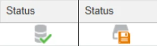
You can get information about the status of your components from the Status column on the 3DEXPERIENCE screen in SOLIDWORKS. If the component was successfully saved to the 3D Space area, you see a green ticked icon as shown on the left in the picture below. If a change was made on the component, you see an orange icon as shown on the right in the picture below. When you hover your mouse cursor over this icon, you can see the “File is modified in session” warning.
When switching from the Part environment to the Assembly environment, since the system detects the changes made, it gives a warning stating that this change made in the Assembly was done without locking and you need to lock the Assembly. After the locking process, the Assembly is saved to the platform.
Step 4: Submitting the Revision for Approval
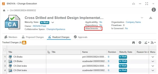
Just as an Issue can be connected to the CA, you can also provide materials supporting the operations performed by adding additional files. When an attachment is added to the CA, the number of attachments is displayed next to Attachments.
As the Design Engineer, I used 3D Markup to explain the changes I made to the Disc and added the markup to the CA.
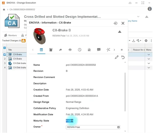
You can see that the maturity states of B revision data located in the Realized Changes area still show as In Work even though they were made Frozen. And you can understand from the exclamation mark inside the orange triangle that this update has not been reflected in this area yet, but it is a tracked operation.
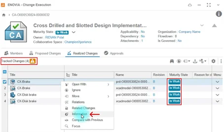
Actually, the data has been frozen in the background; it just hasn’t been reflected in this area yet. The way to see this is by right-clicking the data and selecting Information to examine the properties of the data. As you can see in the picture, Frozen is written next to Maturity State.
Step 5: Giving Revision Approval and Completing the Process
As a result of the examinations made by the Lead Engineer, approval was given to the B revision of the new disc model. The data in the In Work state was promoted to the Released maturity state, just like in the First Release process.
The Issue connected to the CA in Step 2 was automatically promoted to the In Approval state once the CA reached the Completed state. In this way, the designer didn’t need to perform this process manually. With the Lead Engineer’s approval, the Issue opened for development purposes was also completed. Now, a Disc Brake that is more resistant to crack formation and has increased performance is ready for production.
Conclusion
In this blog post, we covered how SOLIDWORKS Users can perform change processes synchronously with ENOVIA applications available with SOLIDWORKS Design and Cloud Services. The advantages and flexibility provided by the 3DEXPERIENCE platform to CAD users are really huge.