

Engineezy is an engineering creator specializing in mechanical and mechatronic builds, including marble machines, robotic systems, kinetic sculptures, and experimental contraptions. Created by Jay Vogler, Engineezy’s website and social channels have become a go-to for makers and general audiences, combining creative design projects with design humor and visual appeal. Vogler was also a keynote speaker at 3DEXPERIENCE World 2026.
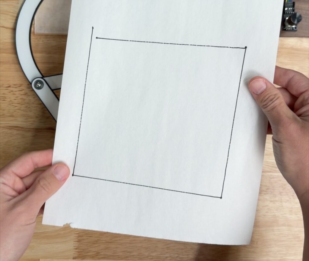
A recent Engineezy project focuses on a specific mechanical challenge: creating a system that draws a perfect square using a single motor in continuous motion. Previously, Engineezy successfully developed a mechanism for drawing perfect circles.
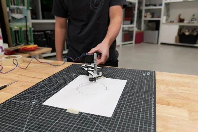
Drawing a square with sharp corners is more complex. Turning the paper can be unreliable and imprecise, causing the corners to drift and leading to accumulated errors. The mechanism needed to automatically draw a square with clean 90° corners using just one motor, without stopping or requiring any adjustments.
The First Pass
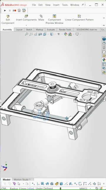
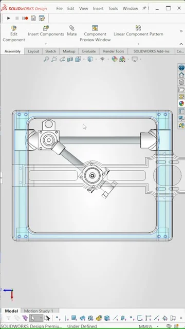
The initial design was built in CAD using SOLIDWORKS. It relied on a motor driving a slider, which connected to a second slider capable of moving along two axes. It looked like a solid CAD design. But when the design was printed and run, the mechanism appeared to draw a circle again, only more complexly. Without elastic tension, the system still followed smooth, continuous motion, which naturally leads to curved paths.
Fixing the Constraint
The next revision addressed a constraint issue. The original cross-slider used a circular rod, which allowed slight rotation within the assembly. Under load, that freedom introduced misalignment and caused binding. Replacing the circular rod with a linear rail removed the extra degree of freedom. Motion was restricted to a single axis, and the mechanism could run without binding.
What Forces the Corners?
With alignment resolved, the remaining challenge was producing sharp corners. A rotating system does not create abrupt directional changes on its own. In this case, the transition comes from elastic tension. As the motor drives the slider, elastics pull the carriage toward the limits of its travel along each axis. When the carriage reaches one of these limits, the tension forces an immediate change in direction. Instead of continuing through a curve, the motion shifts at the extremes, forming distinct 90-degree corners.
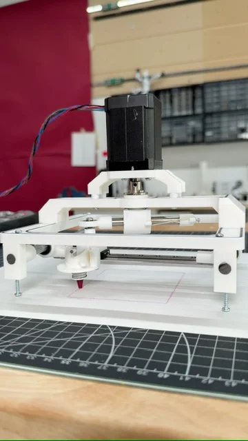
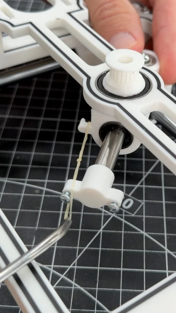
Final build
The entire mechanism was designed in CAD with SOLIDWORKS for Makers. It operates on a single motor and includes a latch that controls when the pen engages with the surface. Once running, it continuously traces a square with consistent edges and corners.
Key learnings from the project:
- Continuous rotation produces curves unless motion is tightly constrained.
- Small freedoms in a mechanism can lead to failure under load.
- Sharp corners can be achieved through force limits rather than by adding control systems.
- CAD plays a direct role in resolving these issues before parts are built.
What shape should I try next?
Check out SOLIDWORKS for Makers, CAD for personal use in Engineezy’s Instagram profile, and use code ENGINEEZY for 20% off
FAQ
How does the mechanism create sharp corners instead of curves?
The elastics pull the carriage to the limits of its motion along each axis. When it hits those limits, the direction changes instead of continuing in a curve.
Why did the original version jam?
The circular rod allowed rotation in the slider. That caused misalignment and binding. A linear rail fixed it by constraining the motion.
Why use a single motor?
It keeps the system simple. The challenge is converting continuous rotation into controlled movement along two axes.
What did SOLIDWORKS for Makers help with here?
Using CAD to design the mechanism was really helpful for adjusting linkages, constraints, and motion paths before printing, also reducing the need for prototyping.