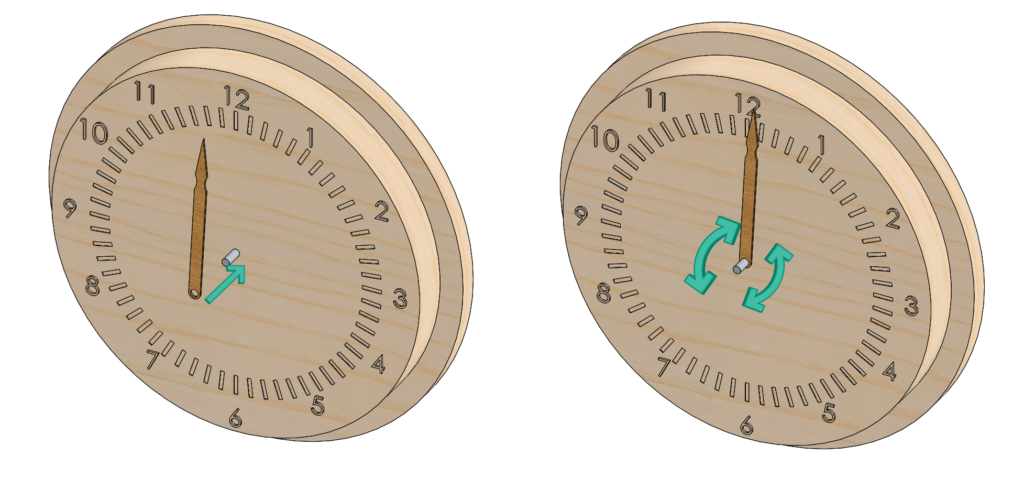

A SOLIDWORKS assembly can appear perfectly healthy. Components are in the right place, mates rebuild without errors and everything moves as expected.
Then, someone makes a design change.
A mate loses its reference. A component stops moving. An over-defined warning appears in a section of the assembly that was not even edited.
The latest change is often blamed for the problem. In reality, that change may simply have exposed a weakness that already existed in the assembly structure.
Stable assemblies are not created by adding more mates or removing every remaining degree of freedom. They come from relationships that clearly describe how the design is intended to behave and continue to make sense as the design evolves.
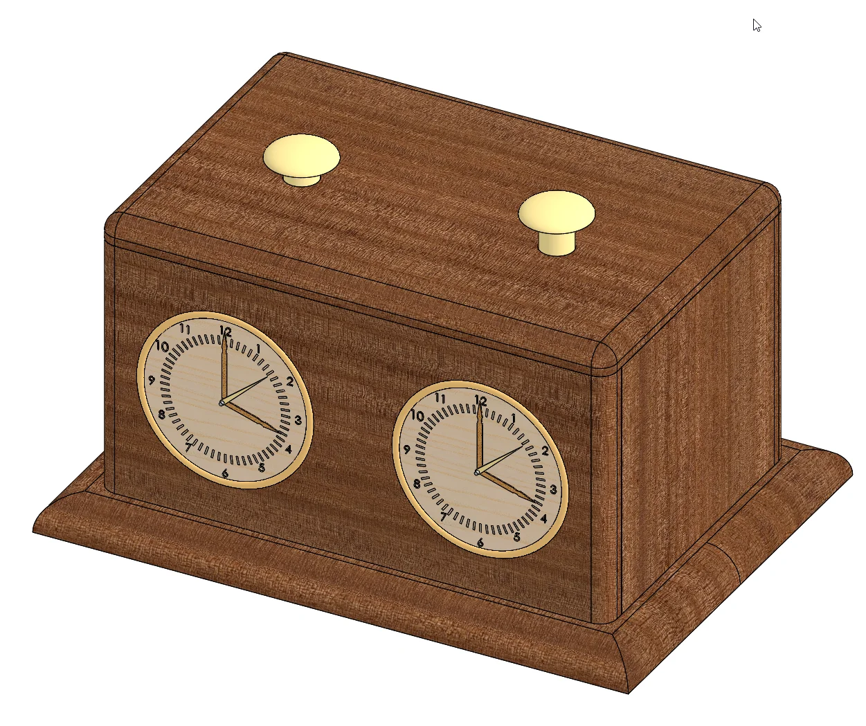
For the examples in this article, we will use the chess clock assembly shown in Figure 1. It contains a simple housing, two clock mechanisms and several moving components. The model is small enough that we can see exactly what each mate is doing while still demonstrating a range of common assembly techniques.
Figure 1. The chess clock assembly used throughout the article to demonstrate mate strategy, intended motion, subassembly behaviour and in-context references.
Start with Motion, Not Geometry
When adding mates, it is easy to focus on geometry. A Concentric mate is added to a cylindrical face. A Coincident mate is added to two planar faces. This continues until the component appears to be in the correct position.
A better question to ask when modeling is, “How should this component be allowed to move?”
Every component inserted into an assembly starts with six degrees of freedom. It can move along three axes and rotate around those same three axes. Each mate removes one or more of those degrees of freedom until only the intended motion remains.
Take the clock hands in our chess clock assembly.
Each hand must be centered on a mounting pin and positioned at the correct distance from the clock face. Start by creating a Concentric mate between the hand and the pin. The hand is now centered, but it can still slide along the pin and rotate around it. At this stage, that remaining movement is useful information.
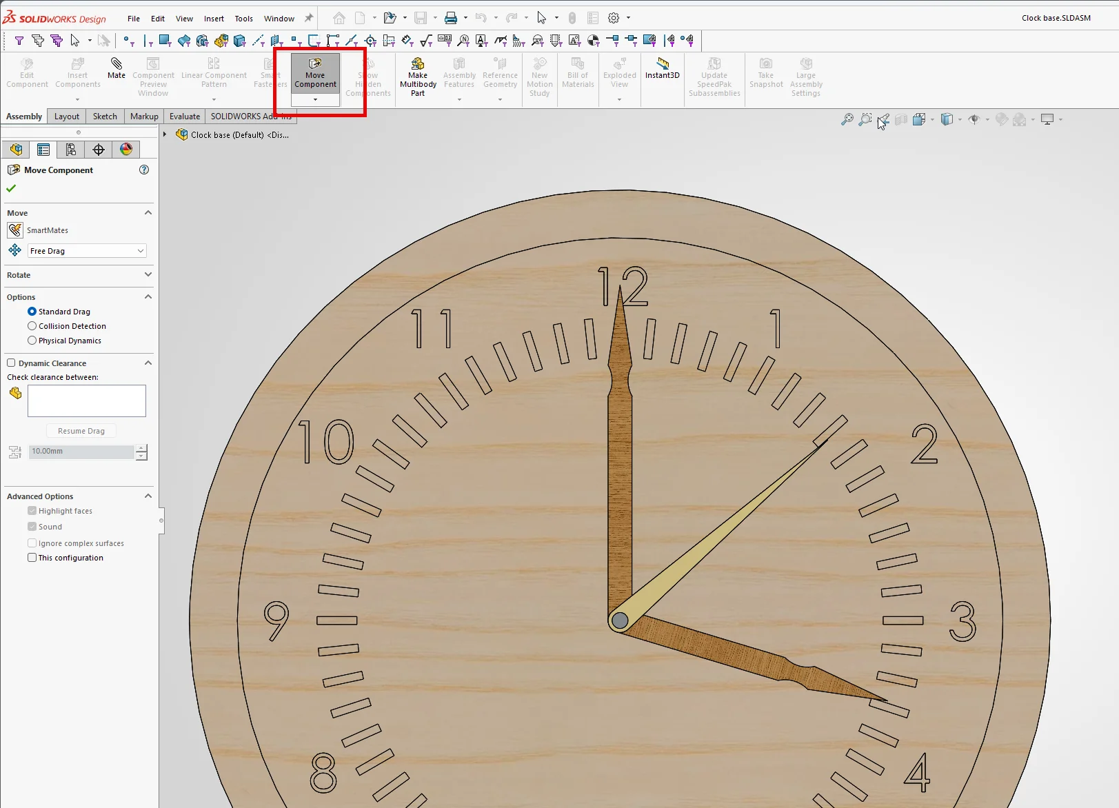
Use Move Component to drag the hand. The remaining movement shows exactly what the mate controls—and what it does not.
Figure 2. Move Component helps you validate the current movement of your components.
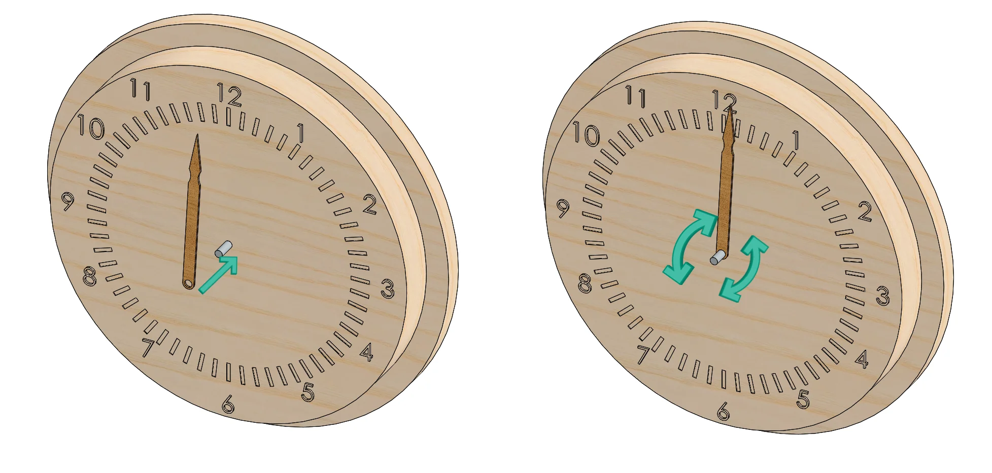
Next, define the axial position with a Coincident or Distance mate. Then test the component again.
The hand can no longer move toward or away from the clock face, but it can still rotate around the pin. SOLIDWORKS may still report a remaining degree of freedom, yet the component is behaving exactly as intended.
Figure 3. A Concentric mate combined with a Coincident mate allows the clock hand to rotate while keeping it correctly positioned.
The remaining motion is not a problem; it is a requirement. That distinction matters because many assembly problems begin when additional mates are added simply because a component can still move. If the remaining motion is part of the design intent, removing it does not improve the assembly. It only adds more constraints for the mate solver to manage.
A useful mate strategy starts with motion, not geometry. Before creating another mate, ask which degree of freedom it removes and whether that movement should be removed.
Fully Defined Is Not Always the Goal
The clock hand remains free to rotate because rotation is part of its function. Other components have different requirements.
Consider the housing of the chess clock. Once the housing panels have been assembled, they should not move relative to each other. In that case, a fully defined condition makes sense because no intended motion remains.
Figure 4. A fully defined assembly is appropriate when no intended motion remains.
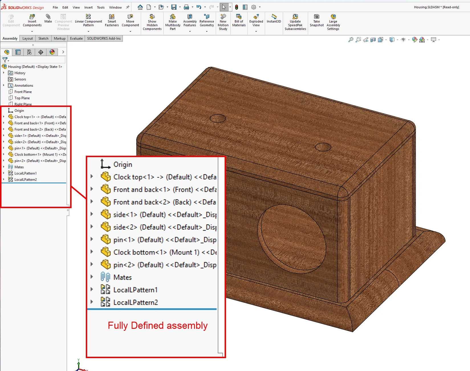
Create the mates needed to position a housing component and verify its behavior using Move Component.
Once the intended movement has been removed, try adding another mate that attempts to control a relationship already defined by the existing mate scheme. Depending on the selected geometry and mate type, SOLIDWORKS may report the component as overdefined or identify the additional mate as redundant.
Figure 5. Adding too many constraints can over-define the assembly, as shown by the extra positioning mate on the gold ring around the clock face.
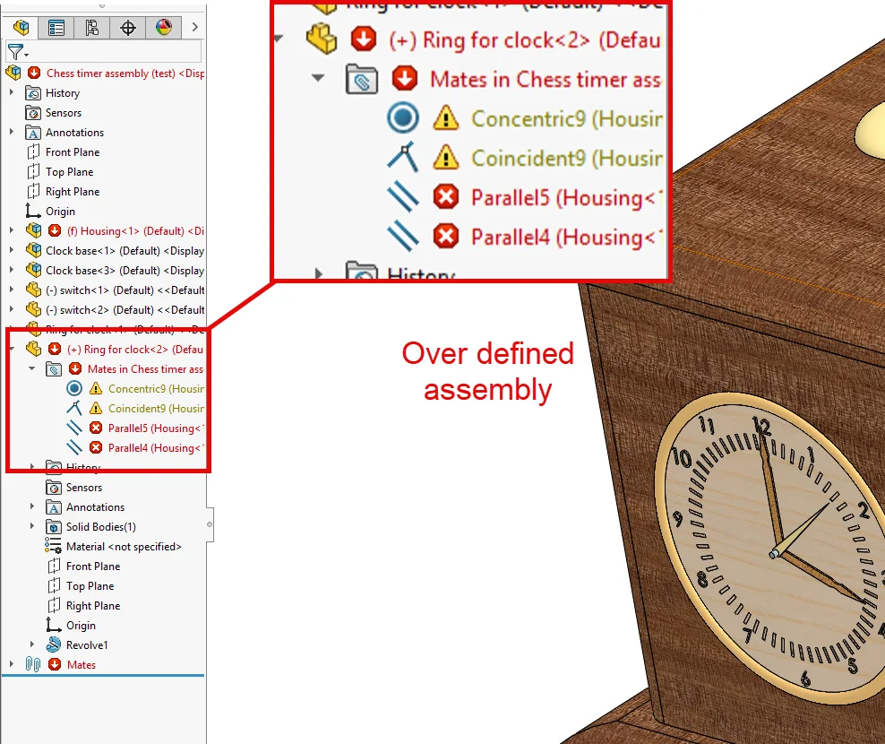
Adding more mates does not make a component safer or more stable, it simply gives the mate solver another relationship to satisfy.
The clock hand and the housing clearly demonstrate the difference. The hand retains a degree of freedom because it needs one. The housing does not exist because no motion remains to preserve. Both are correctly constrained.
An over-defined component is different: multiple constraints are attempting to control the same behaviour, increasing the chance of conflicts as the assembly changes.
You want to keep this point in mind: “Fully defined is a condition. Correctly defined is the goal.”
Understanding Rigid and Flexible Subassemblies
Open one of the clock subassemblies and drag a clock hand. The hand rotates as expected. Then return to the top-level assembly and try again. The hand no longer moves.
The mates have not changed, but the way SOLIDWORKS solves them has.
When a subassembly is set to Rigid, SOLIDWORKS treats it as a single unit at the parent assembly level. Internal mates still determine the positions of components inside the subassembly, but their motion is not solved in the context of the parent assembly.
For the chess clock, this means the hands can rotate when working directly inside the clock mechanism, but not when working from the top-level assembly.
To change that behavior, right-click the subassembly and select Make Subassembly Flexible.
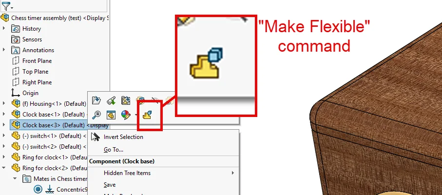
Figure 6. Making the clock mechanism flexible allows its internal motion to be solved in the top-level assembly.
The internal degrees of freedom become available at the higher assembly level, and the hands can once again be rotated from the parent assembly.
This capability is useful, but it comes with a trade-off. Rigid subassemblies can be solved as single units. Flexible subassemblies require their internal mate relationships to participate in the solution of the parent assembly.
The actual impact depends on assembly size and complexity, but larger assemblies with many flexible mechanisms can require additional rebuild time.
In some cases, flexibility may not be necessary. If a mechanism only needs a small number of predefined positions, configurations can provide a simpler solution. In this case, create configurations representing the required states and keep the subassembly rigid.
Figure7. Configurations can be useful when you want to avoid flexible subassemblies.
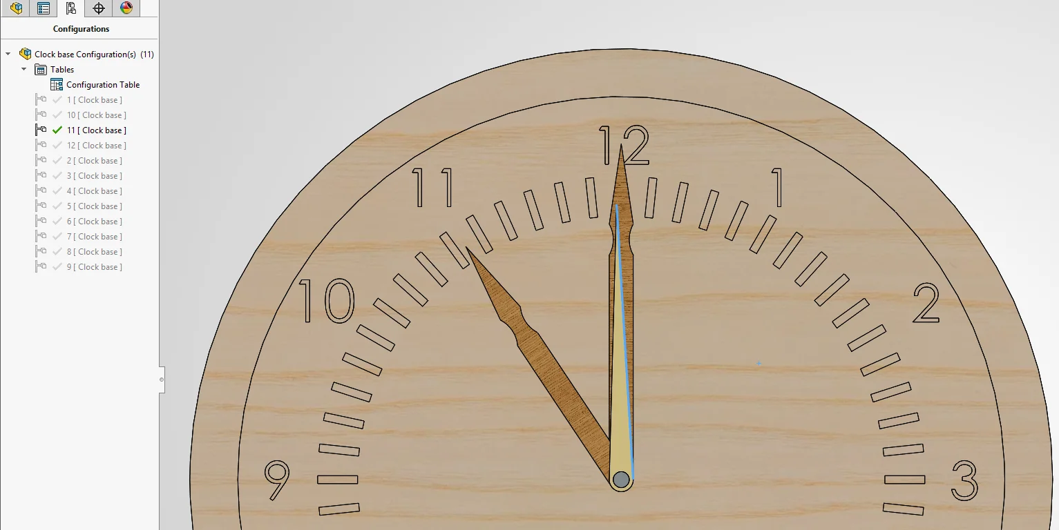
An assembly that only needs an open, closed and intermediate position often falls into this category.
The practical question is: “Do you need continuous movement at the parent level, or only a few defined positions?”
Use the Make Flexible command when the parent assembly needs access to the internal motion. Otherwise, configurations may provide a simpler alternative.
Lock Rotation Without Creating Another Mate
Some components have unwanted movement that is not part of the design intent. The wooden locating pins in the chess clock housing are a good example.
After applying a Concentric mate and defining the axial position of the pin, the component is located correctly but still able to rotate around its axis. One solution would be to add another mate that controls the angular position. In many cases, that is unnecessary.
If the angular orientation has no functional meaning, edit the Concentric mate and enable Lock Rotation.
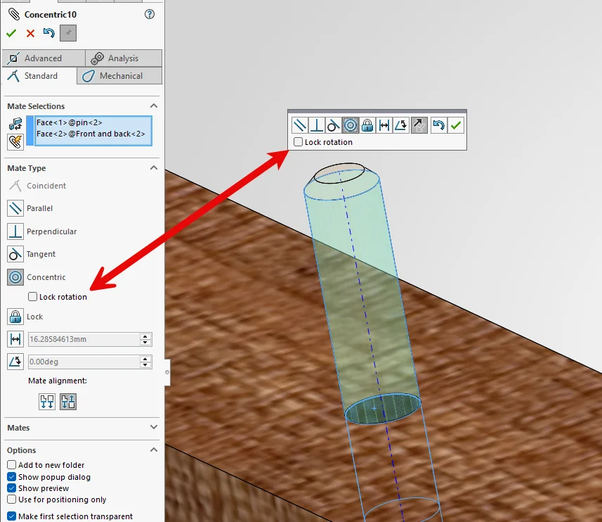
Figure 8. Lock Rotation removes unwanted rotation from the Concentric mate without adding another mate.
The pin can no longer rotate, but no additional mate is created. This keeps the mate scheme simpler and reduces the number of relationships that must be solved and maintained.
However, Lock Rotation should not replace genuine design requirements. If the orientation of a lever, keyed component, or similar part matters, use a mate that explicitly defines that orientation.
The question here is: “Does the rotation need to be defined, or does it simply need to be removed?”
Keep In-Context References Under Control
In-context modeling can remove a significant amount of duplicated work. In the clock housing, for example, pin locations are defined in the Top and Bottom components. The Side panels contain matching holes that must align with those positions.
Rather than recreating dimensions, we can reference the existing geometry when creating the holes in the Side panel.
This establishes a clear dependency of Top / Bottom → Side.
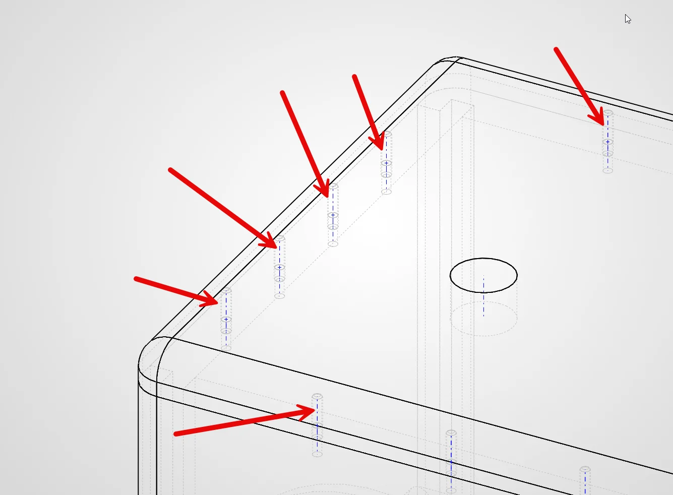
Figure 9. The Side panel holes reference the pin locations from the Top and Bottom components, keeping the in-context dependency direction clear.
Changing a driving hole location automatically updates the corresponding hole in the Side.
The approach is efficient because design information only exists in one place. At the same time, it creates dependencies between components, and those dependencies should have a clear direction.
Problems begin when that direction becomes unclear.
If a later feature in the Top references geometry controlled by the Side, the relationship becomes Top → Side → Top. This creates a circular reference.
Circular dependencies are harder to understand, harder to troubleshoot and more vulnerable to unexpected behavior as assemblies evolve. Before creating an in-context reference, decide which component owns the information.
In the chess clock, the Top and Bottom own the pin locations. The Side follows those locations. Maintaining that ownership makes the dependency easy to understand and prevents the same information from being controlled from multiple directions.
To guide the decision, ask, “Which component owns this dimension or position?”
Once that has been established, let the dependency flow outward from the component that owns the information.
Troubleshoot Mates Systematically
Sooner or later, every assembly contains a mate that cannot be solved. The instinctive response is often to edit the mates highlighted in red until the warning disappears. A better approach is to follow a consistent process.
When mate errors appear:
- Start with the change that triggered the problem.
- Inspect the references used by the failed mate.
- Suppress suspect mates individually rather than entire mate groups.
- Use MateXpert to narrow the search when multiple mates are involved.
- Verify affected subassemblies separately.
- Test the intended motion after the warning has been resolved.
This process focuses on repairing the cause of the problem rather than the symptom.
A mate failure is often the result of a changed feature, lost reference or conflicting relationship elsewhere in the assembly. The warning identifies where the problem appears, and the troubleshooting process helps identify why it appeared.
Build for the Next Change
A SOLIDWORKS assembly is rarely finished after the first successful rebuild. Designs evolve. Components change. Assemblies grow. The decisions made when creating mates, defining motion and establishing dependencies determine how well the assembly handles those future changes.
A stable assembly is not simply one that rebuilds today. Its mate scheme should describe the intended behavior of the design. Its dependencies should have a clear direction. Its structure should make problems easier to isolate and understand.
When the next design change arrives, the goal is not just to avoid errors; it is to ensure the assembly itself helps you understand them.
Build for the next change, not just the current rebuild.