
Bigger Wheels, Bigger Loads: Upgrading a Lawn Tractor Sulky
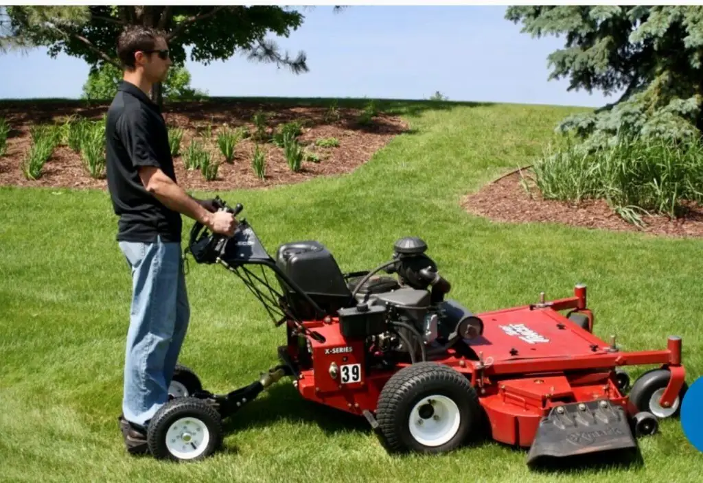
Project images and models courtesy of Don Bartlett
A lawn tractor sulky is one of the simplest pieces of equipment you can find: a platform, a seat, and two wheels. However, for retired engineer Don Bartlett, the issue lay with those wheels.
Although the sulky was functional when hitched to his lawn tractor, every bump in the yard was translated to the operator. The small wheels often dropped into ruts, bounced over roots, and transformed minor bumps into large jolts. The initial solution was to replace the small wheels with larger ones. However, what started as a simple wheel replacement quickly evolved into a complete structural redesign.
Larger Wheels Introduced a New Challenge
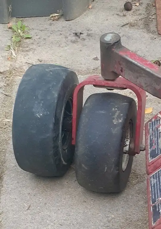
Left – wheel from a castor from a Gravely tractor that was used for this project. Right – caster from an Exmark tractor.
The replacement wheel came from the caster assembly of a Gravely mower. On the original mower, this wheel was supported on both sides by a clevis. However, the sulky used a completely different support arrangement: the axle is supported only from one side. Using a larger wheel already introduces more leverage than a smaller one, and supporting it from one side adds another load path. This meant that Don’s comfort upgrade became a more significant engineering challenge: he needed to determine whether the sulky frame could withstand the new forces introduced.
Fabricating a New Mounting Block
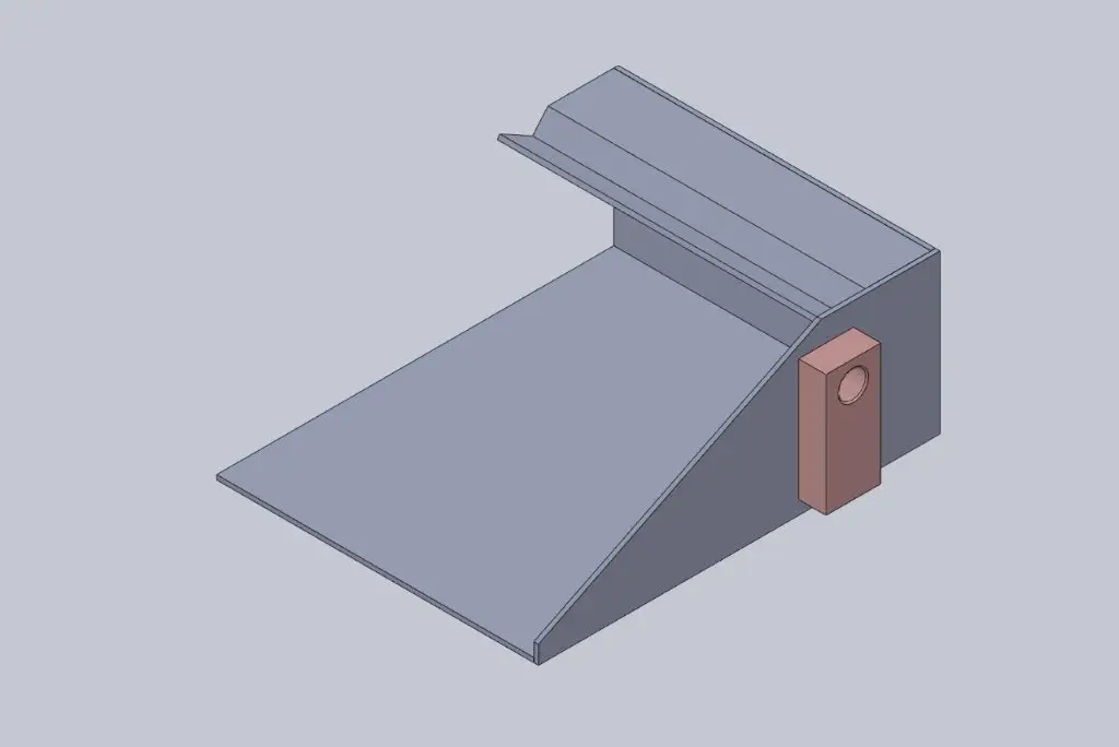
The original sulky featured a small support block for the axle mounting (shown above).
While this worked well with the factory wheel size, Don had concerns about its suitability for the larger-wheel configuration. To better distribute the load across the structure and minimize the risk of the side panel flexing under pressure, he fabricated new steel blocks. These blocks are connected to the top, bottom, front, and sides of the sulky box (below).
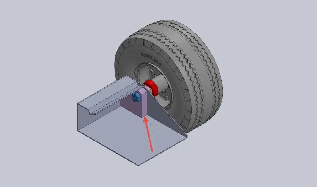
Although this small enhancement may go unnoticed in the finished machine, it is crucial to ensuring the wheel upgrade’s durability.
Building an Axle From a Bolt
Don chose an 11-inch Grade 8, 3/4-16 UNF bolt to serve as the axle for the new wheel setup. With a tensile strength of 150 kilograms per square inch (KSI), this bolt provides the necessary strength.
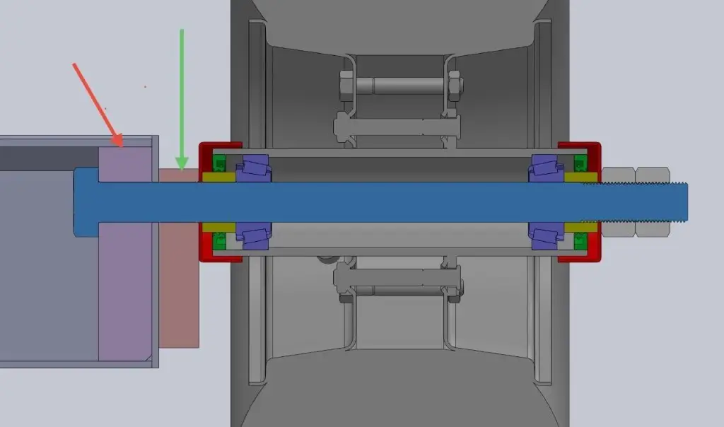
Cross section of axle. The red arrow points to the new block that was added to better support the axle.
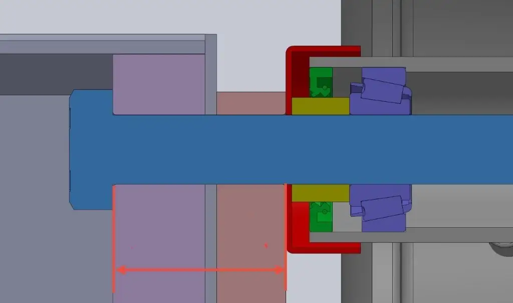
Close up of left side of shaft. The arrow shows the portion of the shaft that will have Loctite applied to glue the shaft to the sulky box.
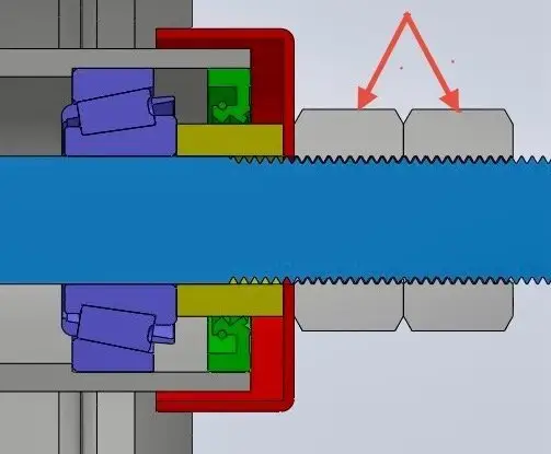
Close up of right side of shaft. The function of the left nut shown by the red arrows, is to adjust the two tapered roller bearings, to remove the clearance in the bearings. The second nut on the right acts as a jam nut, to lock the first nut in place to preserve the bearing adjustment.
The wheel operates on tapered roller bearings. One nut is used to adjust the bearings and eliminate any clearance, while a second nut locks that adjustment in place. This design detail is commonly found in many automotive and industrial applications. Proper bearing preload is essential, as it affects wheel life, rolling resistance, and long-term reliability.
Welding, Machining, and Custom Tools
Don’s fabrication process involved nearly every area of the shop. He cut reinforcement blocks to fit snugly against the sulky box. Any existing holes in the scrap steel were welded shut before the blocks were installed. Don used Dual Shield flux-core welding to attach the one-inch-thick blocks to the 1/8-inch-thick sulky structure, choosing this method specifically for its deep penetration.
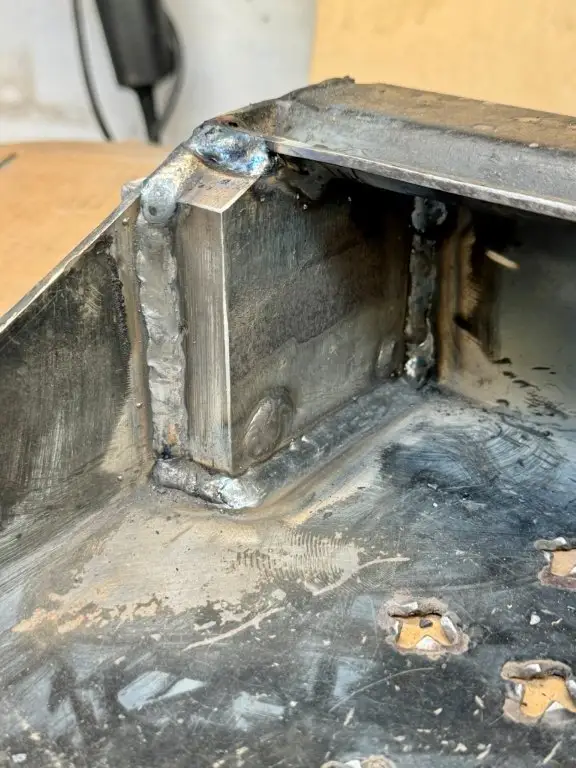
Welds on the left block: Dual Shield Flux Core wire (FCAW-G) was used to attach the 1” block to the 1/8” sulky box.
Instead of drilling, he machined the axle bores to their final size. After initially drilling undersized holes, he bored them to achieve the precise fit needed for the axle assembly.
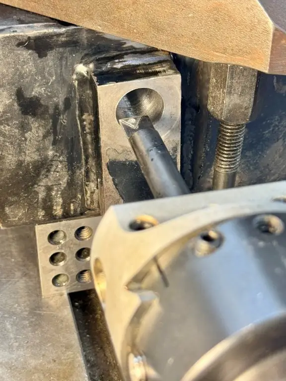
Boring the 0.75-inch hole in sulky box
Even the installation of the seals used a specially designed tool. This approach highlights the maker mindset: makers often go beyond simply modifying machines; they often create their own tools specifically for the modifications.
CAD to the Rescue
Projects like this show why many makers prefer to use CAD in their process. Changing the wheel diameter might seem like an easy fix, but it can affect how much weight the wheels can handle, require adjustments to the mounting structure, and mean you’ll need new parts to make everything fit properly. Understanding these relationships before cutting any metal is much easier than discovering issues after everything has been welded together.
Back to Smooth Sailing…or Mowing
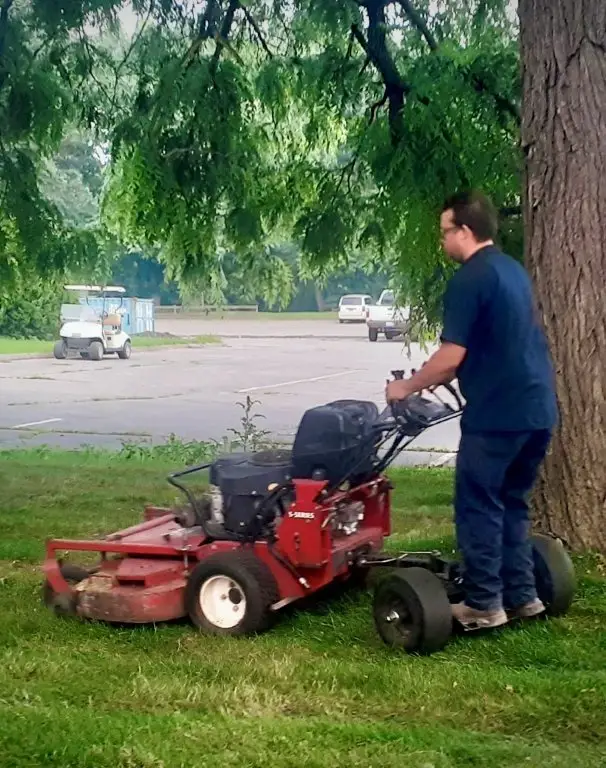
The finished sulky (above) now rides on tractor-sized wheels instead of the original smaller ones. The larger wheels smooth out rough terrain, while the reinforced structure supports the additional loads they introduce.
Larger wheels led to structural analysis, fabrication work, machining operations, bearing setup, and custom tooling. That’s often how home engineering projects go. The first idea is simple. The interesting work happens underneath it.
What Projects Are You Ready to Tackle?
Don Bartlett spent 44 years as a Senior Staff Engineer at FANUC America and has used SOLIDWORKS for nearly three decades. He has also spent decades doing what many makers do after hours: looking at a piece of equipment and figuring out how to make it better.
His sulky upgrade began with installing larger wheels to improve the ride. Along the way, it turned into a project involving structural reinforcement, machining, welding, bearing setup, and custom tooling. That’s often how home projects go. What begins as a small upgrade can quickly become a series of design decisions where fit, strength, and assembly all matter.
SOLIDWORKS for Makers gives you the same CAD tools used by engineers and product designers, priced for personal use at $48 USD/year. Whether you’re building equipment for the yard, parts for the garage, or fixtures for the workshop, you can work through the details before making the first cut.
Learn more about SOLIDWORKS for Makers.
FAQ
What is a lawn tractor sulky?
A sulky is a two-wheeled platform that attaches to the rear of a lawn tractor or mower. The operator rides on the sulky instead of walking behind the machine.
Why use larger wheels?
Larger wheels roll over uneven ground more smoothly than smaller wheels. In this project, the goal was to reduce the impacts transmitted to the operator while mowing.
Why did the sulky need reinforcement?
The new wheel arrangement created different loads than the original design. Larger support blocks were needed to distribute those loads across the sulky structure.