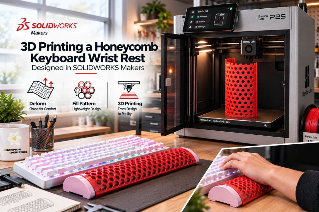

It started with a simple idea: why not design my own keyboard wrist rest?
I wanted a wrist rest specifically for my workstation, with controlled dimensions, an ergonomic shape, and a lightweight design that I could 3D print and actually use.
The height difference between my keyboard and desk was causing wrist discomfort, especially during long hours of blogging and editing. So, instead of looking for a ready-made solution, I decided to design my own.
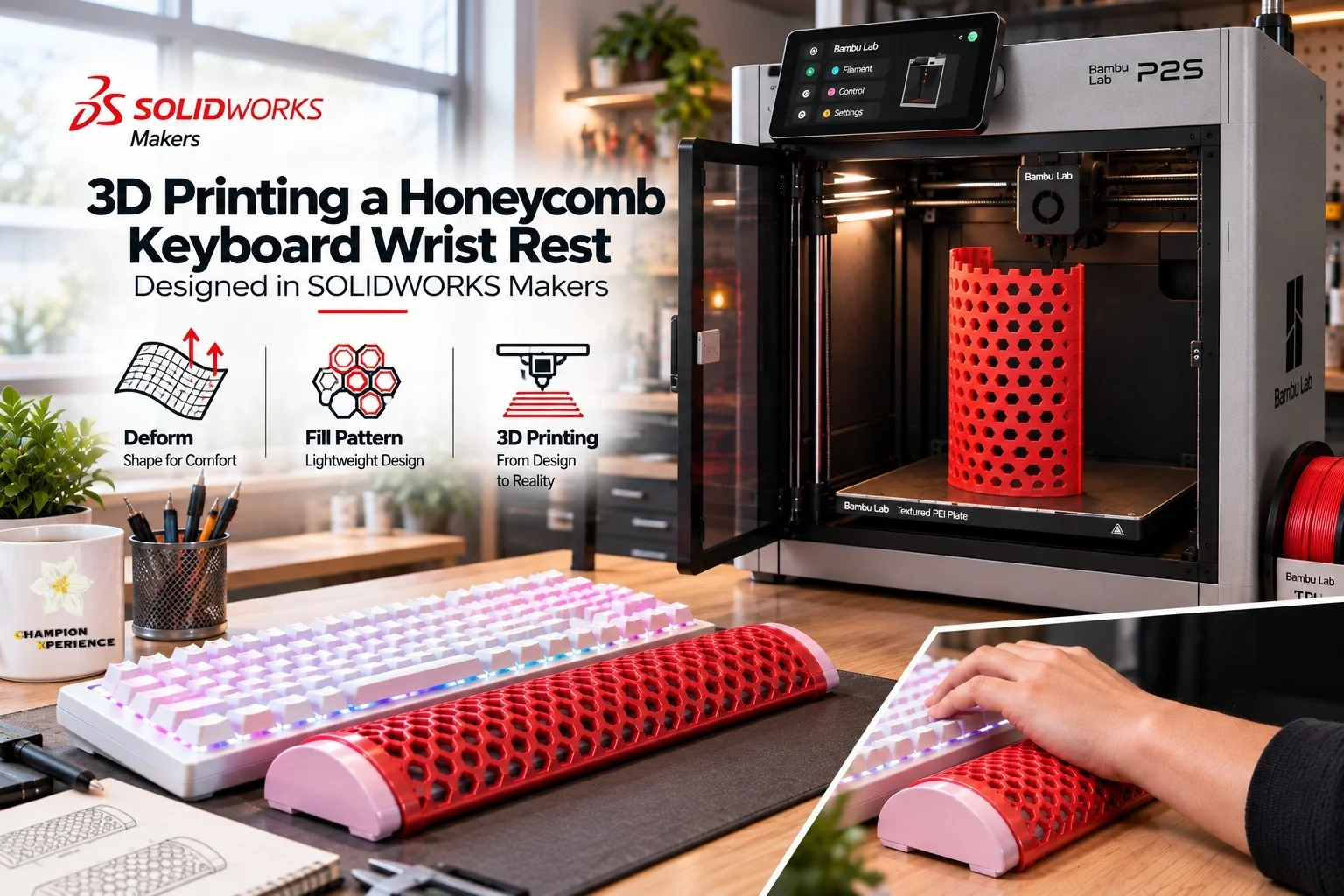
For the project, I used SOLIDWORKS for Makers for CAD design and a Bambu Lab 3D printer to produce the parts, using PLA for the structure and TPU for the wrist-contact area.
I also wanted to experiment with an ergonomic curved surface and a honeycomb structure.
So, let’s start with the design.
Why Did I Choose a Honeycomb Structure?
I chose the honeycomb pattern not only for its appearance, but also to keep the wrist rest lightweight and reduce material use. The flexible TPU material also works well with the patterned structure, making the wrist contact area more comfortable and breathable.
This project also allowed me to combine several SOLIDWORKS commands, including Split, Swept Surface, Fill Pattern, Ruled Surface and Deform.
Before creating the honeycomb structure, however, I first needed to determine the basic dimensions.
Designing the Ergonomic Shape
The first thing I did was measure my keyboard. My keyboard dimensions are approximately:
- Thickness: 20 mm
- Height including the keys: 30 mm
- Width: 390 mm
Based on my research, I decided the wrist support area should be approximately 50–60 mm wide.
For my first design, I selected a wrist support width of 60 mm. I also set the maximum height of the wrist rest to 20 mm because I didn’t want it to exceed the height of my keyboard.
At this point, I wasn’t trying to create the final version immediately. I wanted to create a first version, print it, and see how it actually felt.
This is an important part of the workflow for me because the CAD model can look correct on the screen while still not feeling right when you actually use it.
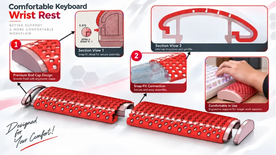
Figure 1: Overview of the Keyboard and Honeycomb Wrist Rest.
- First Prototype
For the first prototype, I reduced the overall width so that I could produce a test print more quickly. After printing and testing it, I noticed two things. First, the wrist-support area was not large enough. Second, the height of the wrist rest needed to be increased. So, I returned to SOLIDWORKS Makers and modified the design.
- Refining the Wrist Support Shape
For the revised design, I created a more pronounced ergonomic profile.
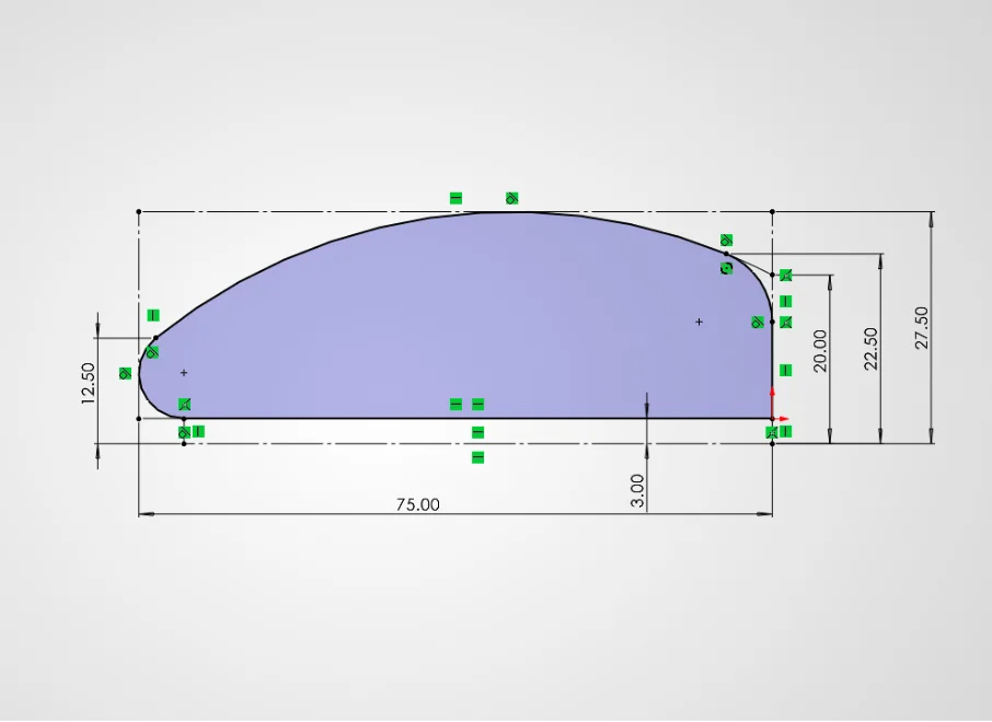
Figure 2: Ergonomic Wrist Support Shape.
If you look at the final shape, the bottom surface that contacts the desk is flat. This provides a stable base for the wrist rest.
On the keyboard side, the surface is higher and then slopes downward. I wanted this transition to be gradual rather than creating a sharp change in height. I also rounded the outer edges to make the shape smoother and more comfortable.
The upper wrist support area has a wider raised section where the wrist rests. From this raised area, the surface gradually slopes downward toward the ends.
This increases the contact area and creates a smoother transition between the raised wrist support area and the desk. There is also a rectangular feature underneath the flat area of the design, which you can see represented by dashed lines in the model. I created this feature as a reference for the feet that would be added later.
- Checking the Section
I also used a sectional view to check how the different components would fit together.
In Section View 1, you can see the interface between the components. For this connection, I used a 0.075 mm interference-fit clearance. The goal was to create a connection that would hold the parts together without using screws or adhesive. Of course, the exact fit can depend on the printer and printing parameters, so this is the value I used for my prototype rather than a universal recommendation.
Designing the Wrist Rest for My 3D Printer
There was another important limitation that I needed to consider before finishing the model.
My Bambu Lab printer has a 256 mm × 256 mm print area, while my keyboard is approximately 390 mm wide. That meant I couldn’t simply create one 390 mm wide wrist rest and send it to the printer. I therefore decided to make the wrist rest as a multi-part design. I also wanted to avoid screws and adhesive.
The idea was simple: Design the connection directly into the geometry.
This meant that the two printed sections could be assembled after printing.
Splitting the Wrist Rest into Two Parts
Since the wrist rest was too wide for my printer, I used the Split command in SOLIDWORKS to divide it into two parts.
I then designed male-and-female connections so that the sections could slide together and lock in place, without needing screws, bolts, or adhesive.
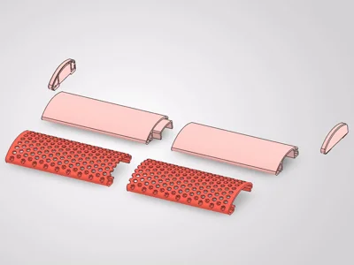
Honeycomb Keyboard Wrist Rest Assembly.
Designing the TPU Wrist Support
The next part of the design was the surface that would actually contact my wrists.
I didn’t want this area to be made entirely from rigid PLA. For this reason, I created a separate TPU component. TPU is flexible compared with PLA, making it more suitable for the wrist contact area of this particular design. But using two different materials also created another CAD challenge.
I needed to make sure that the TPU component could be installed into the PLA body and remain in position during normal use.
Creating the TPU Channel
In the PLA component, I created a channel where the TPU part could slide into position. The TPU component was designed with complementary geometry so that it could fit inside this channel.
In Detail 2, you can see the section through this connection. I used a 0.10 mm fit clearance between the TPU component and the PLA channel. If the TPU component needs to be easier to remove and replace later, I would consider increasing this clearance to approximately 0.15–0.20 mm, depending on the actual printing result.
The advantage of making the TPU component removable is that it can be replaced later if the material becomes worn. But at this point, there was another question:
How could I create the hexagonal pattern on the TPU component while still following its curved shape?
This is where the Deform command became important.
What Is the Deform Command?
The Deform command in SOLIDWORKS allows you to modify existing geometry by controlling how it is displaced or reshaped.
Instead of manually rebuilding the geometry, you can use Deform to transform an existing model using different types of references. SOLIDWORKS provides three main deformation methods:
- Point
- Curve to Curve
- Surface Push
For my wrist rest project, I used Curve to Curve. Before showing how I used it, let’s briefly look at the other two options.
Point Deform
The Point option allows you to deform a model by controlling the movement of selected points. You can use it to push or pull a specific area of the model, creating localized deformation without remodeling the entire component.
To better understand how the Deform command works, we can look at the result after selecting Maximum Stiffness and confirming the command.
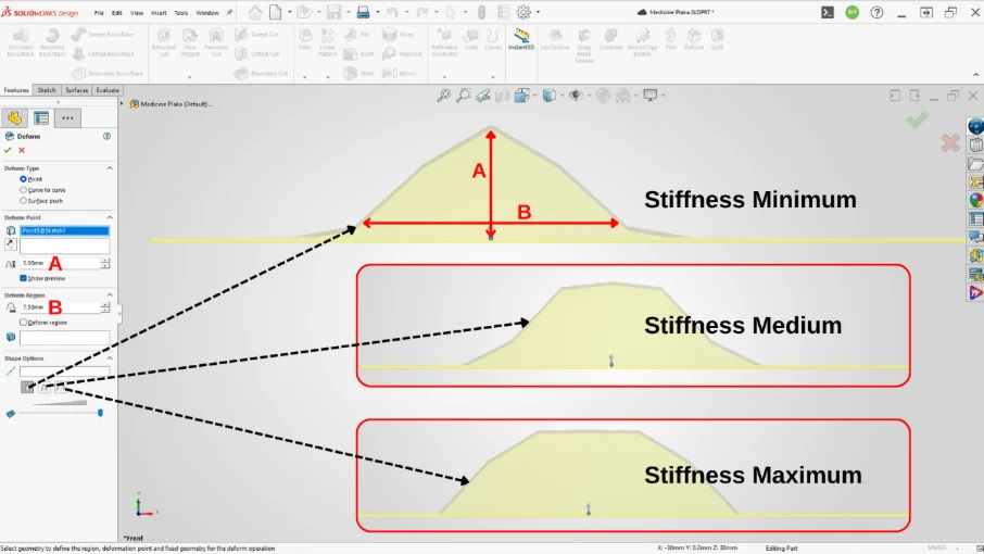
Figure 3: Different Shape Options in SOLIDWORKS Deform command.
At first glance, the results from the Point and Surface Push options may resemble a Punch operation in sheet metal. However, the behavior is actually different. The Deform command can be applied to either a surface or a solid body, and it does not require the model to maintain a constant thickness.
If we look closely at the area highlighted with the magnifying glass in the image above, we can see an organic, wrinkle-like deformation forming on the surface. Rather than creating a punch feature, the Deform command stretches and reshapes the existing geometry to produce the desired deformation.
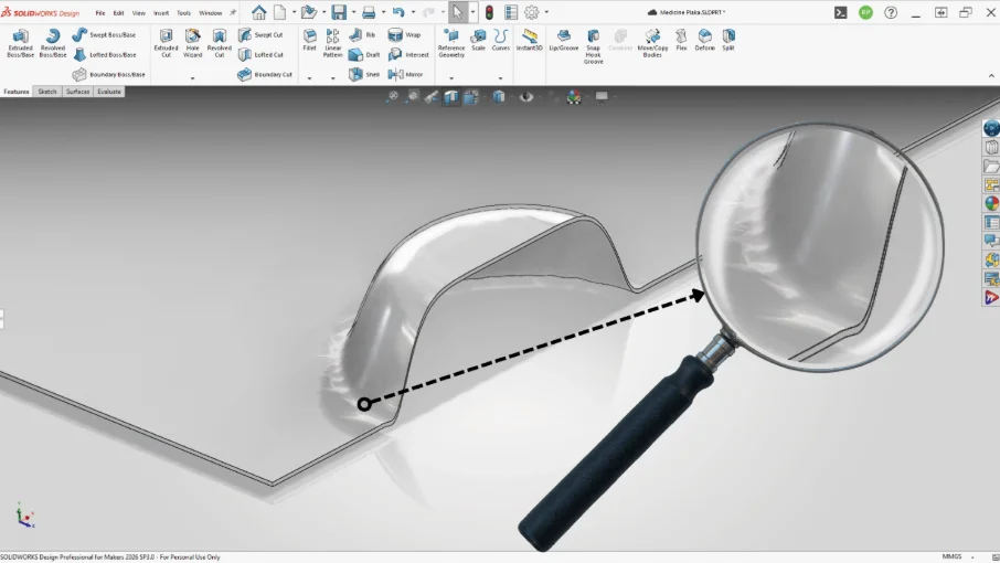
Figure 4: The highlighted area shows how the Deform command stretches and reshapes the existing geometry.
Surface Push Deform
The Surface Push option allows you to deform a surface or solid body by using another body as a deformation tool. Instead of controlling individual points, you can define a Deform Region and use a selected tool body to push into or away from the target geometry.
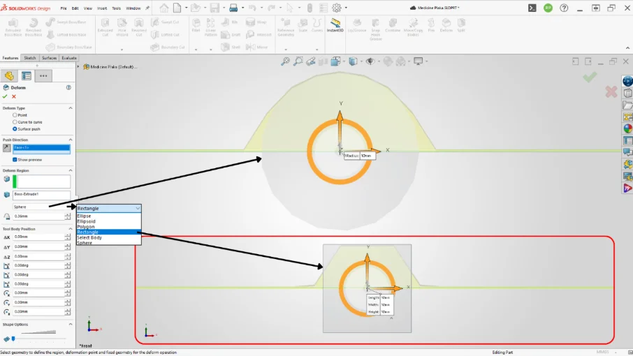
Figure 5: Surface Push – Deform Regions, Rectangle and Sphere examples.
Within Surface Push, you can either select one of the predefined geometric shapes or use your own geometry with the Select Body option. This makes the method useful when you want to create a specific shape or imprint on an existing model.
In the following example, I use four cylindrical bodies as the tool geometry to create recessed shapes in a thin plate.
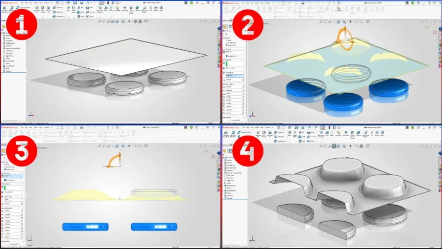
Figure 6A: Cylindrical bodies used to form the recessed features.
Step 1:
We have a square plate with a thickness of 0.20 mm and four cylindrical bodies. The goal is to use the cylindrical shapes to create recesses in the plate.
Step 2:
Within the Surface Push command, select the edge of the plate that is perpendicular to the cylinders as the Push Direction. You can also select a surface if preferred.
In the Deform Region field, select the plate as the Body. Then, using the Select Body option, select the four cylindrical bodies.
A coordinate system (gizmo) appears on the cylindrical bodies. Move them 22 mm upward in the Y direction. This value controls the height of the resulting deformation on the plate. You can also check and adjust this value in the Tool Body Position field within the Deform command.
Step 3:
After confirming the deformation, you can see the effect of the cylindrical bodies on the plate. The cylinders create recessed shapes through deformation, but the resulting shape does not completely wrap around the cylinders.
To control this result, we can adjust the Deform Deviation value in the Deform Region section.
The deviation value cannot be set to 0. If you enter 0, SOLIDWORKS displays a warning and shows the minimum deviation value that can be accepted. You can then set the value according to the desired result.
When the deviation is set to its minimum value, the deformation of the plate approaches the shape of the cylindrical tool bodies.
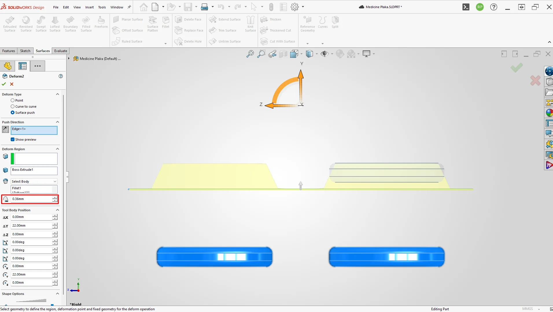
Figure 6B: Deform Deviation.
Step 4:
After confirming the command, you can clearly see the deformed recesses created by the cylindrical bodies on the plate. This demonstrates how Surface Push can use existing geometry to reshape another body without manually rebuilding the affected area.
Curve to Curve
The Curve to Curve option deforms existing geometry by mapping one set of curves to another. It reshapes the model so that selected edges or curves follow the target curves’ shape and position. This is useful for transferring a shape onto curved geometry without manually remodeling it.
In this section, I demonstrate step by step in the video how the honeycomb-patterned wrist support was modeled. Therefore, I’ll focus only on the key points, rather than going into every detail.
As I explained earlier, the part that will rest on the wrist will be made of TPU. I want this part to feature a honeycomb pattern, which helps prevent sweat buildup during use and creates a breathable product, while also resulting in a more visually appealing design.
As you can see in the image, I’ve positioned a flat plate tangent to the Wrist Rest part. I’ll create the honeycomb pattern on this plate. To do this, I’ll use the Fill Pattern command.
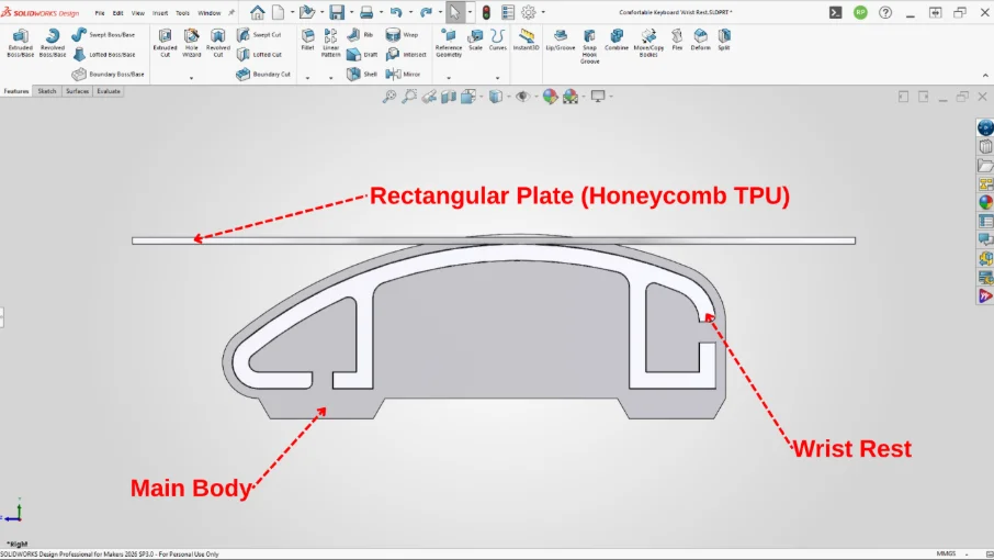
Figure 7: Preparing the reference surface for the honeycomb pattern.
Honeycomb with Fill Pattern
Within the Fill Pattern command, we can select predefined geometric shapes. After selecting the polygon shape, I set the number of sides to 6.
One thing to note about the Fill Pattern command is that it does not work on surfaces with zero thickness. That’s why we used a solid body in this step.
In the Deform command, we created a zero-thickness offset surface on the plate to facilitate working on a curved surface.
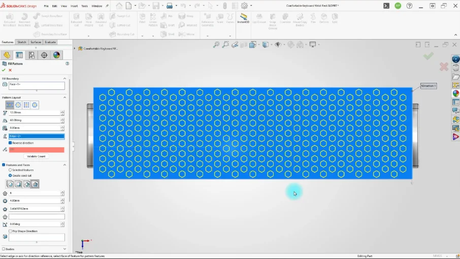
Figure 8: Applying Fill Pattern with a six-sided polygon.
Curve to Curve with Deform
In the Curve to Curve command, we select the edge of the plate that will be deformed according to the curve, as well as the curve on the Wrist Rest body.
Since we want the deformation to spread evenly on both sides, we check the Uniform option.
To perform the same process for the left side, we need to click the “+” button shown in the image in the Deform Curves section. After doing this, you can also select the edges and curves on the left side.
Keep in mind that the Uniform and Stiffness settings are reset with the new selection, so you’ll need to select them again.
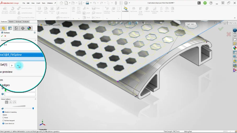
Figure 9: Adding a second Curve to Curve selection.
After confirming the command, the flat honeycomb body follows the curved shape of the Wrist Rest. This allows me to create the honeycomb pattern on a simple flat body first and then adapt it to the curved geometry.
Preparing the TPU Body
Before assigning thickness, we need to create a design that allows the Honeycomb TPU body to fit into the channels in the Wrist Rest body and prevents it from coming out.
Therefore, we created the areas that will extend into the channels using the Sweep Surface and Ruled Surface commands, with the Wrist Rest body as the reference.
We then completed the design by extruding the surfaces to a thickness of 3 mm.
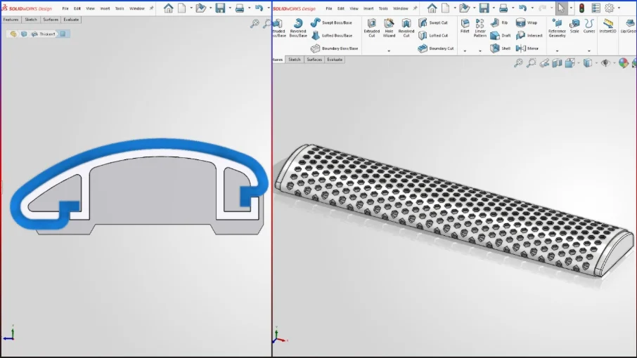
Figure 10: 3D models of the honeycomb keyboard wrist rest.
Checking the Final Geometry
Once the deformation was complete, I checked the wrist support shape, honeycomb pattern and TPU-to-PLA interface. I made sure the honeycomb followed the intended curvature and that the TPU insert could slide into the channel and stay securely in place.
At this point, the model was ready for 3D printing.
Preparing the Model for 3D Printing
I divided the final model into three printable components: two PLA sections for the main structure and one TPU component for the wrist support area.
My husband, Ridvan Polat, also helped with the 3D printing process and settings, using his experience to fine-tune the PLA and TPU prints.
After printing and assembling the parts, the Honeycomb Keyboard Wrist Rest was ready to use.
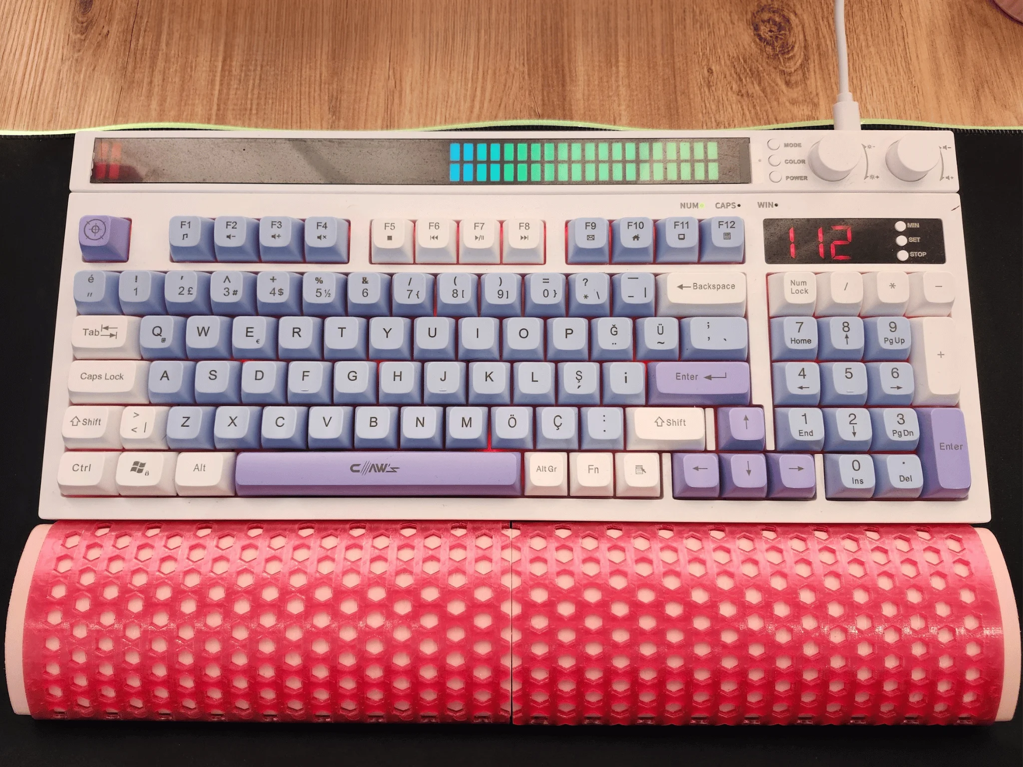
Figure 11: Final 3D-printed Honeycomb Keyboard Wrist Rest.
Print the Model
If you want to print the wrist rest yourself, I also uploaded the model to MakerWorld. You can download the files and try the design on your own 3D printer.
Conclusion
This project turned a simple everyday problem into a complete CAD and 3D printing project. Using SOLIDWORKS for Makers, I designed, tested and refined the wrist rest. I combined PLA, TPU and several SOLIDWORKS commands to create the final part I now use at my workstation.