The Misaligned Mate in SOLIDWORKS 2018


The Misaligned Mate is a new mate introduced to the mating ecosystem in SOLIDWORKS 2018. In short, it’s a pair of concentric mates that have been relaxed so that the axes aren’t perfectly in line. Meaning that components that do not have identical hole centres can now be mated to one another.
An example of this could be imported, or “bought in” components, where modifying the centre to centre dimensions is not viable. Let’s look at an example of a sink and a mixer tap, where the holes in the sink are 145mm centre to centre, while the tap is 150mm centre to centre. In terms of absolutes, there is a 5mm disparity between tap pipe and sink hole centres. Prior to SOLIDWORKS 2018 fully defining the two components via concentric mates would be impossible and a workaround would have to be employed.
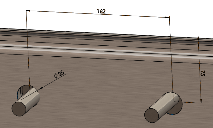
However, in reality a 16mm pipe in a 25mm hole means you can move the pipe up to 4.5mm off centre in any direction:
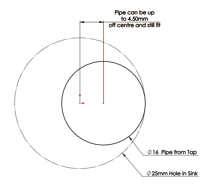
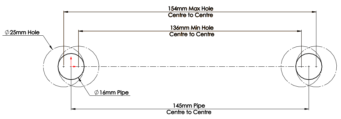
Meaning in this example the holes on the sink could vary anywhere between 136 and 154mm, and the tap would still fit…
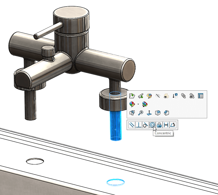
…and this is where the Misaligned Mate comes in: With SOLIDWORKS 2018 we can apply a concentric mate to one pipe/hole set:
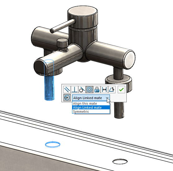
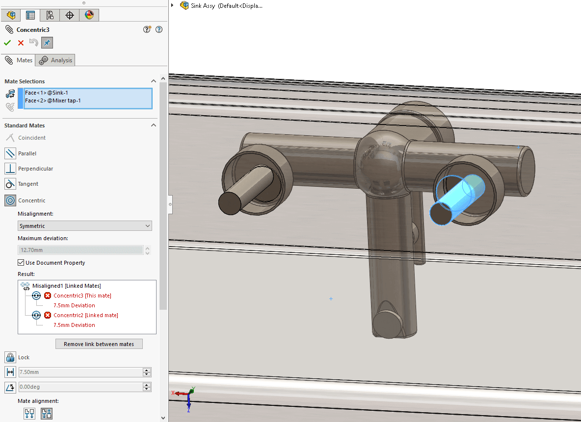
Then when we attempt to apply one to the other set we get an additional line in the pop-up menu giving the option to make it misaligned:
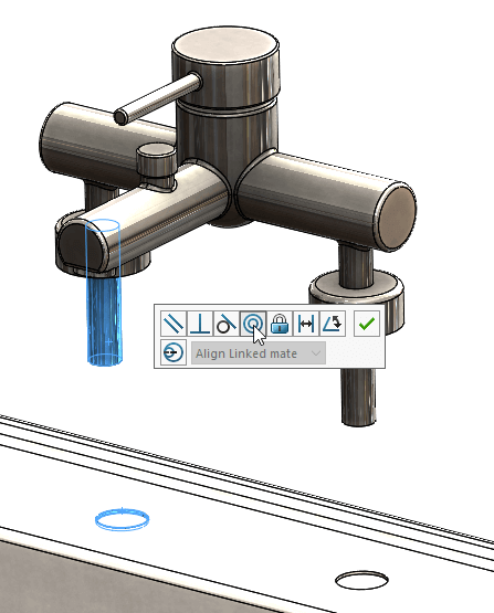
Toggling this on then activates the pull-down menu next to it giving three options:
- ‘Align This Mate‘ – aligns the current mate; pushing all misalignment on the first (linked) coincident mate.
- ‘Align Linked Mate‘ – aligns the first (linked) mate and all the misalignment is placed on the current mate.
- ‘Symmetric‘ – splits the misalignment between the two.
For the purposes of this example the symmetric option is the one to go for as the disparity between centres is too great to be accommodated all at one end:
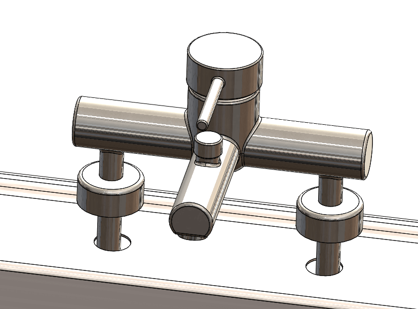
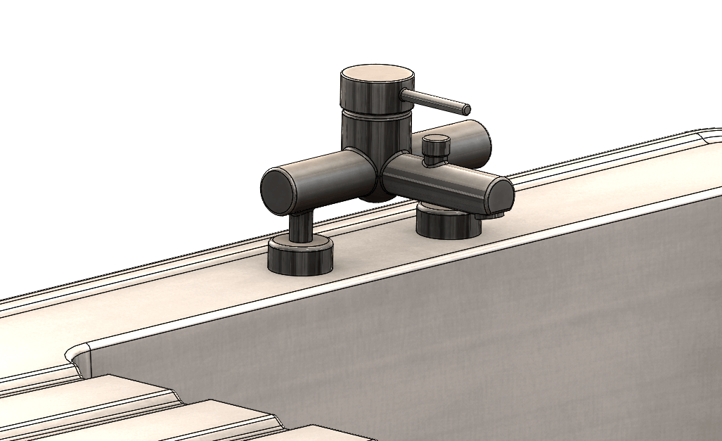
Finish off with a standard coincident mate and it looks fine from above:
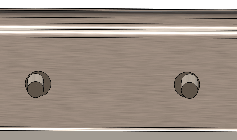
And from underneath we can see the pipes are easily accommodated by the holes in the sink:
There is one thing to note however -While this is an excellent and (by some) long awaited addition to the mating system, it is not fool proof. There is the provision of a ‘Maximum deviation’ within the properties (the default value being 12.7mm) so you can set that to help avoid interference. If set correctly the mate will error if the combined deviation is greater than the maximum set. In this case the holes in the sink have been set at a centre to centre of 135mm resulting in a deviation of 7.5mm per hole, a total of 15mm causing the mates to error:
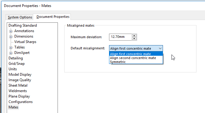
Setting the maximum deviation is easy enough. You can do it for the entire document in Tools > Options > Document Properties > Mates. You can also specify the default mate behaviour – ‘Align first concentric mate‘, ‘Align second concentric mate‘, or ‘Symmetric‘.
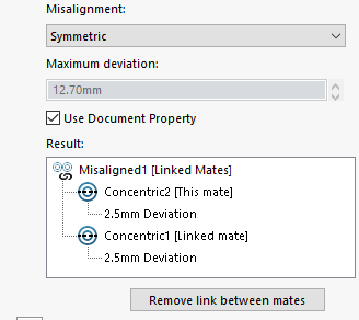
Or you can apply a value to a specific mate. After applying the Misaligned mate, edit either of the linked concentric mates (click on it in the Feature tree and select ‘Edit feature’ from the pop up menu)>Untick the ‘Use Document Property’ and then specify the desired value in the Maximum deviation box.
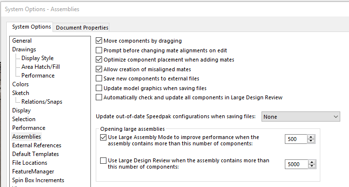
You can also disable the feature completely from the System Options: Tools > Options > System Options > Assemblies, and untick ‘Allow creation of misaligned mates’.
However, if you keep them active and neglect to set the maximum deviation or set it incorrectly and this results in the maximum value being greater than the tolerance the components afford you (as with this example where the sink has been modified so the holes are a little further apart) the pipes will clash with the sink, but the misaligned mate won’t error.
So treat it with care, use interference detection between the components after mating them and remember – with great power comes great responsibility!
We hope you found that useful!
Have you seen our blog archive where we have posted plenty of helpful articles? We also have a fantastic video library filled with easy-to-follow videos on a number of topics inspired by other SOLIDWORKS users – take a look. Also, don’t forget to follow Innova Systems on Twitter for daily bite size SOLIDWORKS tips, tricks and videos.
Latest posts by Innova Systems (see all)
- Duplicating a SOLIDWORKS Assembly Project - August 20, 2018
- SOLIDWORKS 2018: The Bounding Box tool - July 24, 2018
- The Misaligned Mate in SOLIDWORKS 2018 - June 16, 2018