SOLIDWORKS 3DEXPERIENCE Solutions: Create Designs Quickly – With Simple and Flexible Tools


A critical aspect of effective conceptual design is being able to explore many ideas quickly, without disrupting your creative thought process. The freedom to easily develop, evaluate and communicate your ideas results in more innovation, and ultimately, better designs.
SOLIDWORKS 3DEXPERIENCE solutions deliver this design freedom as they are built around the Single Modeling Environment (SME). SME incorporates simple, integrated design workflows into a clean modern UI, allowing you to rapidly explore many design options. SME eliminates the need to define your product structure prematurely, when the definition of discrete parts and assemblies are still in a state of flux, and concentrate on the process of design. These include:
SME allows you to choose the right tools and workflow for your design process:
- 2D or 3D
- Freehand or sketching
- Prismatic or freeform shapes
- Multi-body or assembly
- Master model, bottom-up or top-down
Within the SME you can create sketches or solid bodies in the same design tree, to build a single component (part) or multi-component assembly. Using SME, you are free to immediately start designing and add the product structure when needed.
Typical SME Workflows:
Sketching
Many design ideas start as a simple napkin sketch!

By incorporating both freehand and precise, parametric sketching capabilities directly into SME, you can quickly start to document and share your ideas, then leverage this information using the integrated 3D tools as you explore further.
Sketch to Components
When you decide that your design is ready for more refinement, you can easily convert your 2D sketch objects into discrete components using the ‘Sketch to Components’ tool.
A common scenario for using this approach would be to start out with a 2D mechanism, then with a couple mouse clicks switch to a 3D motion study. SME converts the 2D components, motion setup and assembly mates to 3D equivalents, saving you valuable time and effort.
Multi-body Modeling
Early stages of design are a perfect fit for SME. Imagine being able to focus 100% of your attention on solving your project goals, not on the part and assembly structure. While multi-body modeling might not be unique to SME, the level of ease and efficiency it brings are unparalleled.
With SME, you can create features that span across multiple bodies. If you decide to convert these bodies into separate components, the sketches and features are pushed to the components automatically for you.
But wait there’s more, if you need to move features from one component to another, simply drag and drop between the components and your work is done. This level of design flexibility is what separates SME from other modeling environments.

Bottom-Up Assembly Design
This is one of the most common workflows. Bottom-up assembly design allows you to create assemblies in several different ways.
- Basic Bottom-Up Approach:
- Create separate components or import existing geometry
- Insert multiple components into a document (physical product)
- Position components with assembly mates
- Using Pre-defined Primitives:
- Create components quickly using pre-defined ‘primitives’
- Combine simple shapes like blocks, cylinders and links to represent your components
- Position components with assembly mates

- Make Component:
- Design using multiple bodies in a single physical product
- Use the ‘Make Component’ tool to convert bodies to components
- Position components with assembly mates
Top-Down Assembly Design
This workflow often involves combining multiple modeling techniques.
For example:
- Create a layout sketch to present key component locations
- Use ‘Sketch to Components’ tool to create discrete components
- Add purchased components using the ‘bottom up’ technique
- Add new components using external references to create ‘top down’ components
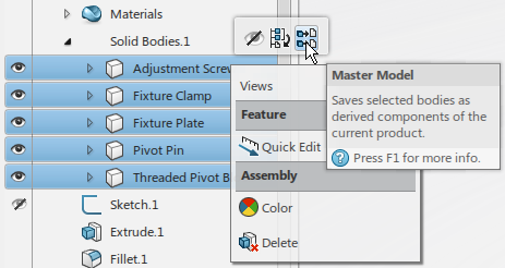
Master Model Design:
There are situations where it is easiest to create all components in a single, multi-body physical product. Once defined, the multiple bodies are converted to components (derived) using the ‘Master Model’ tool. This technique works best for designs that do not involve motion.
This workflow allows you to keep both the bodies and derived components in a single physical product. The derived components can be modified (e.g. – add post-assembly features), but most editing tasks are performed at the body level, which then drives the changes to the respective components.
:")
Summary:
The single modeling environment simplifies your process by allowing you to create complete designs in a single physical product. It doesn’t matter if the design was created using sketches, a single solid body, multiple solid bodies or multiple physical products combined in an assembly; SME handles it all.
The use of one workflow over another is typically a matter of user preference. That being said, there are certain workflows that are better suited for specific tasks.
Below is a table for guidance:

Watch this short video to see how the flexibility of the single modeling environment will help you design faster and more productively that ever before. Most importantly, it allows you to focus on your design, not CAD!
SOLIDWORKS Conceptual Designer and Industrial Designer are the safest and most reliable choices to compliment your SOLIDWORKS Desktop design environment.
Read this white paper to find out how design engineers can do even more within the the Single Modeling Environment.

John Picinich
Latest posts by John Picinich (see all)
- Parametric or History-Free Modeling? Why Not Both with Direct Editing - July 16, 2015
- Smart Assemblies that Learn How You Work - June 23, 2015
- SOLIDWORKS 3DEXPERIENCE Solutions: Create Designs Quickly – With Simple and Flexible Tools - April 28, 2015